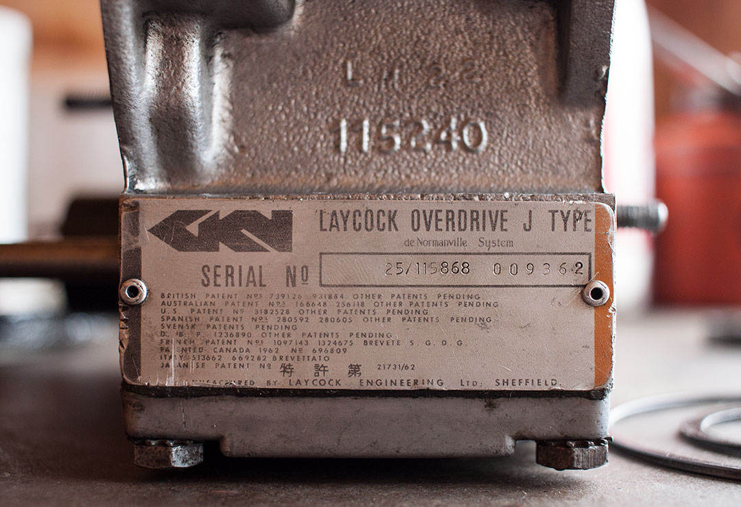
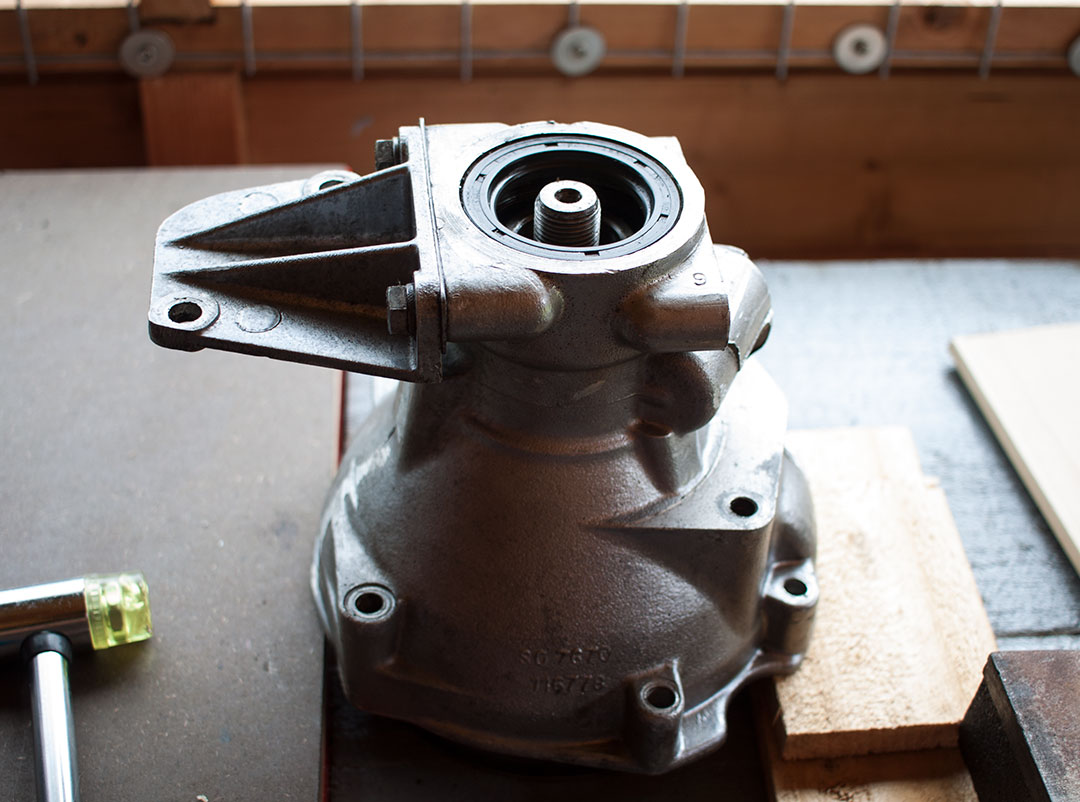
Once the gearbox was complete the overdrive was next up. It’s a Laycock J type used on many cars of the era. Mine always worked quite well so I wasn’t expecting to find anything particularly out of order. It basically consists of an epicyclic gear system which allows the input shaft to reduce speed by about 25% in 3rd and 4th gears. Much better for cruising.
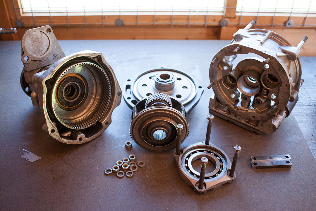
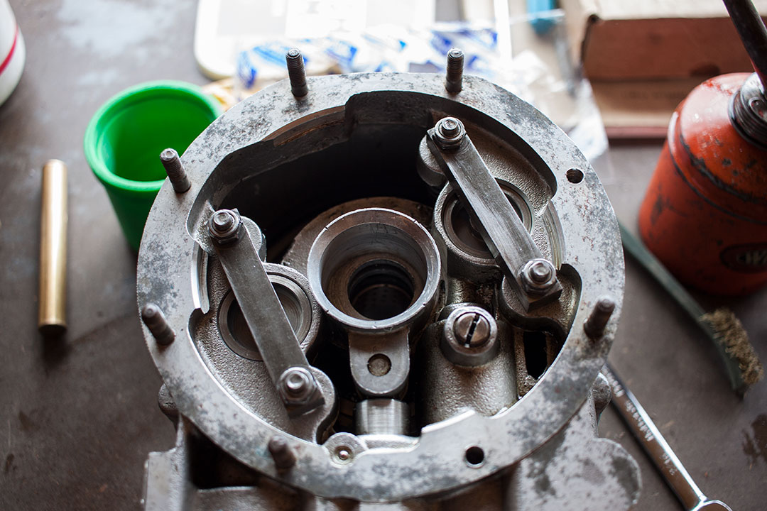
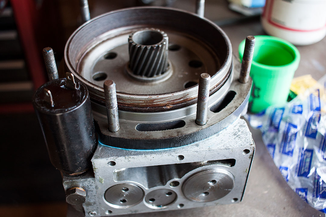
As I’d already stripped the gearbox down, the overdrive was removed and ready to be worked on. First off was to remove the rear case from the main case which pulls apart to separate the main case, brake ring and rear case. Next was the bearing carrier for the cone clutch. This is operated hydraulically by two pistons which push against two bridge pieces spring loaded against the bearing carrier. I removed the four nuts and the bearing carrier and cone clutch could be removed. I removed the bearing from the cone clutch just by removing the circlip.
While I had it in bits my plan was to at least replace all the bearings and clean out the various oil filters. I replaced the O-rings on the two pistons also. There appeared to be plenty of material left on the cone clutch. The annulus and brake ring looked okay. I replaced the sun wheel simply because it was cheap for new-old stock part at £7 and that meant a new bush also. It’s just held in with a snap ring so easy to replace too. I removed the speedo drive, cleaned that up and replaced the sealing O-ring also.
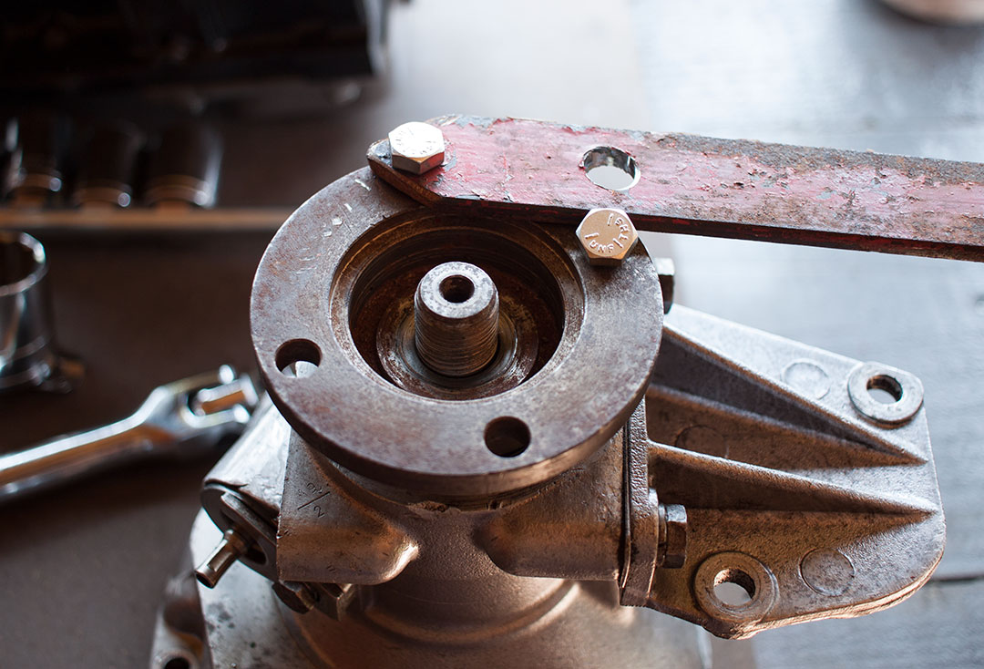
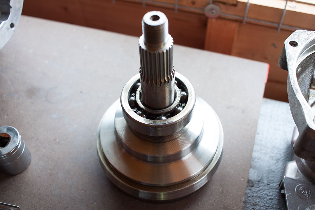
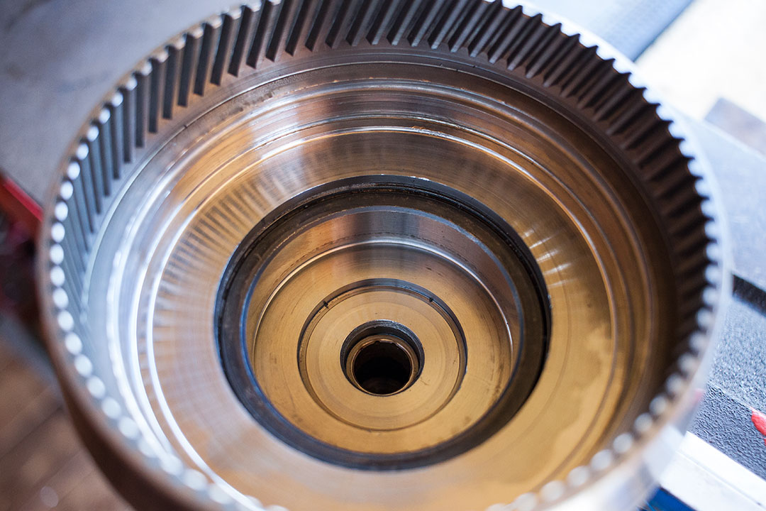
Next up was to remove the annulus from the rear case. I used a piece of steel I had lying around from when I did the camshaft on the Golf and used that to prevent the flange rotating while I unbolted it. I supported the casing between the bench and a piece of wood and carefully knocked the annulus through with a small soft mallet.
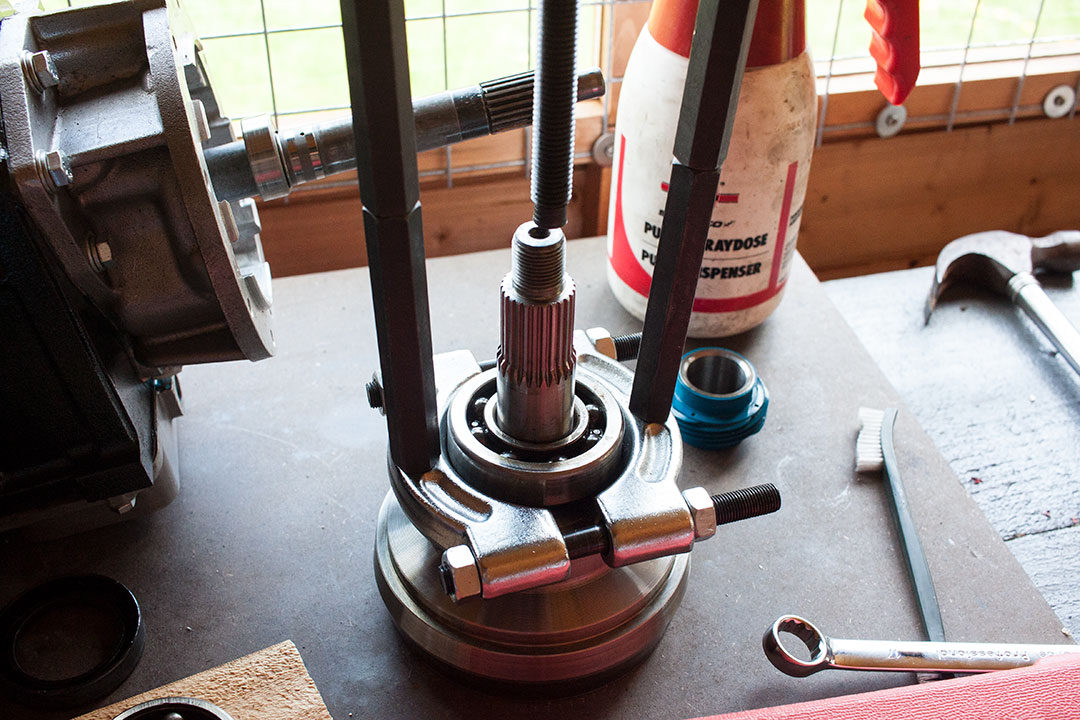
I had new bearings for the rear casing. I didn’t find them too difficult to source online just from part numbers. The outer one can be knocked through with a brass drift. The inner one came out on the shaft of the annulus when I did mine. Another job for the invaluable bearing puller. The speedo drive gear and spacer should just slip off. The oil seal just pops out.
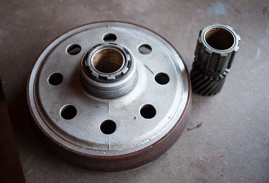
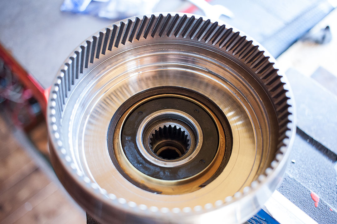
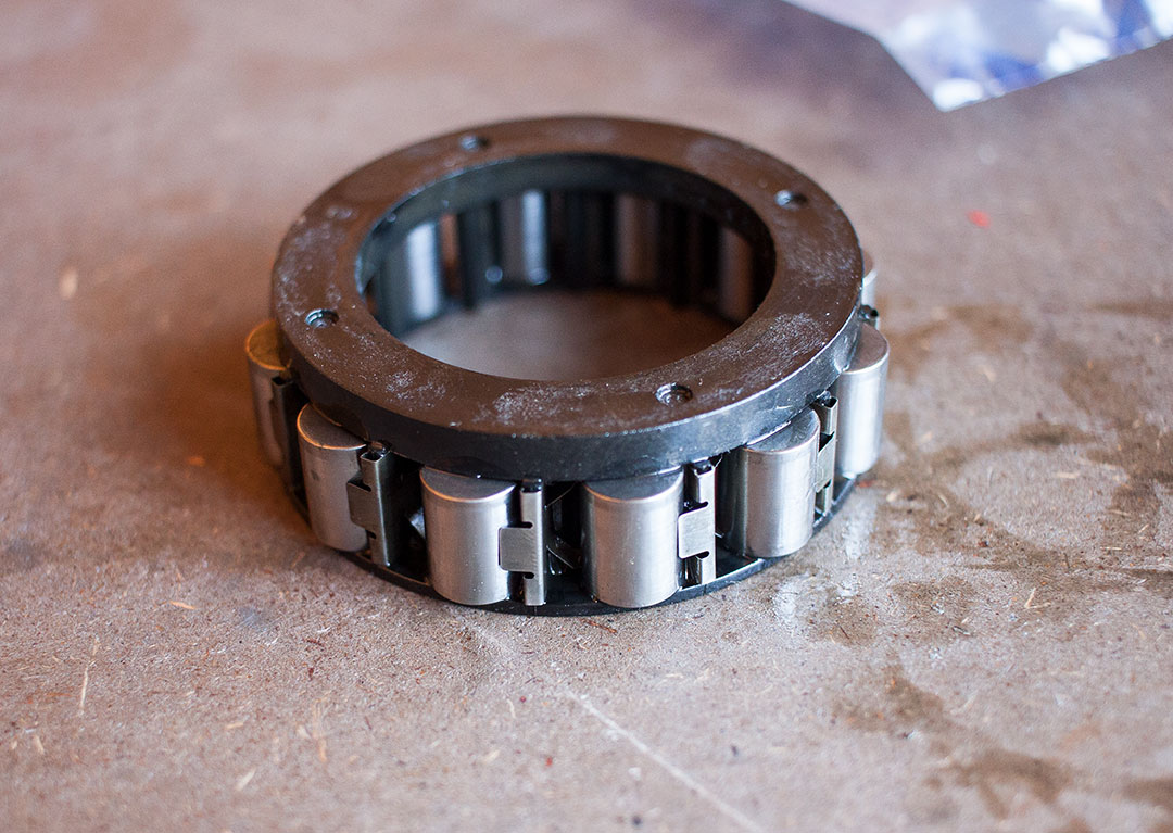
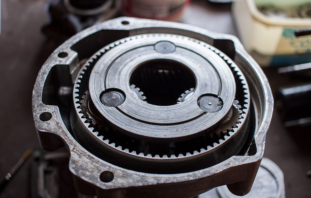
Within the center of the annulus is a sprag clutch. This one-way clutch is used to take up some of the driving load to the output shaft when the overdrive is engaged. If the one-way clutch wasn’t there, the cone clutch would have to take on all the driving load of the input shaft and would slip—or it would have to be much larger to accommodate it. It also prevents operation in reverse if the overdrive were to be engaged as it would break some components (which is not possible anyway due to the isolating switch that limits its use to 3rd and 4th gears only).
I removed the sprag clutch by removing the circlip and brass oil thrower first—cleaned up inside and replaced all twelve rollers.

Now that was sorted the annulus could go back in with the new bearings, speedo drive gear and spacer. The speedo drive gear goes back in the the plain boss facing the inner bearing (towards the gearbox). I fitted a new oil seal to the rear casing and cleaned up the flange where it seats. The torque spec for the flange nut is between 80 and 130 lbf.ft (108 to 176Nm) which seems like a pretty broad spec to me! I set my toque wrench to 100 lbf.ft and tightened the nut. There’s a definite stop when the nut has come to the end of the threads so I don’t think it’s particularly essential to get this exactly right. It’s not like the pinion shaft on the diff where you have two tapered roller bearings and must get it just right.
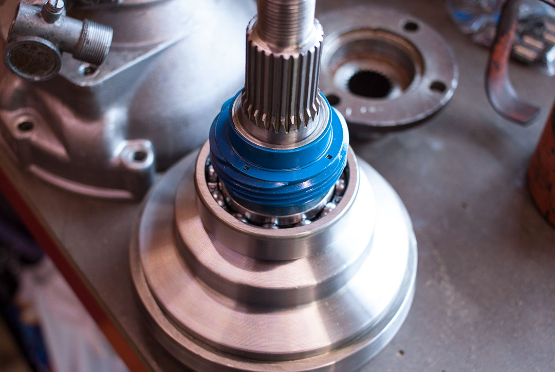
The cone clutch and bearing carrier fitted with a new bearing could go back together and then fitted back to the main casing along with the two hydraulic pistons. The two bridge pieces could be fitted and the bearing carrier bolted in. You can just about push the carrier through against the springs to get the locking nuts started on the thread. The brake ring had a new coat of paint on the external surface fitted before the cone clutch with two new gaskets and a smear of instant gasket just to make sure.


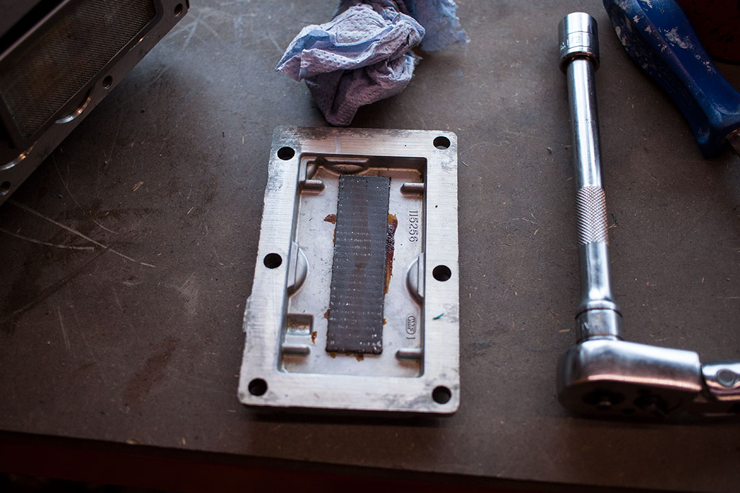
The planet gears with their carrier just slipped in to place with a few drops of oil. The two halves could now be bolted together with new nuts and washers. All that was left was to clean out the two gauze oil filters in the sump. The sump also contains a small magnetic strip to catch any odd bits floating around.
The sump is easily removed with one of the gauze filters. The other filter is under one of the screw caps which are supposed to have a special tool for removal. A couple of small bolts spaced apart the right amount on a piece of flat steel is what I used though. The two other screw caps contain the pressure relief valve and a non-return valve for the pump. As these parts are expensive I decided to leave them be. I can always replace them later on as they are easily accessible also.
I found both filters well clogged with clutch material and bronze from chewed synchro rings in the gearbox. So much so I wouldn’t be surprised if the oil flow was restricted. The circular one actually had a hole in it though so I replaced that (£17, ouch!).


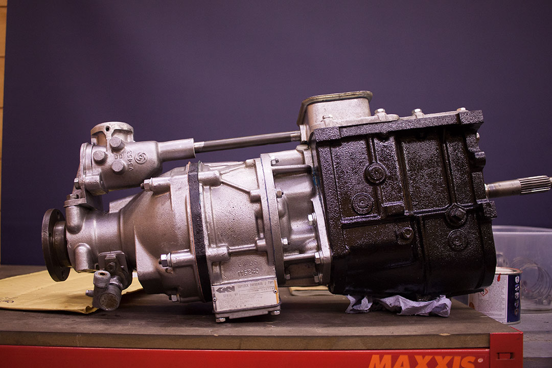
A new gasket for the sump along with some new bolts and the overdrive was pretty much there. All that was left to do was to bolt it back together with the gearbox, fit the gear stick housing and selector shaft. Now it’s ready to bolt in to the car with the bell housing once that’s done. I’ll wait until I have it back with the chassis before I bolt the very heavy, cast iron bell housing on to it and fill it with oil. I’ve been pretty meticulous with the cleaning and painting as I’ve gone along with this and I think it shows. It’s certainly in the best condition it’s ever been while I’ve owned the car. I just hope the time and effort pays off when I come to drive it and I end up with a nice slick gearbox and overdrive.
The engine and carbs are next. I’ve already got the camshaft I want to use which is basically a MKIII profile ground on to a large journal cam. It has a bit more duration than the stock 1500 one. I’ll see how it goes with that. The block is ready and cylinders glaze-busted. The conrods are balanced and polished. I just need to source a set of new pistons and get the crank ground and balanced. I have already made a start on the carbs which is basically just giving them a thorough clean and replacing gaskets. I have slightly richer needles for them to go with the cam and ported head so the old girl should be a bit more sprightly when I’ve finally got her back on the road.
19 thoughts on “Overdrive Rebuild”
Excellent article with great photos.
Don’t forget the sprag clutch is also used during the change in and out of overdrive otherwise there would be a loss of drive.
Good point. Thanks Paul!
hello.
can you please help me.
i have been contacting many car owners and web sites trying for a few months to find out how hot a J type overdrive should get when being used.
i have one on my volvo p1800 and the gearbox is fine and doesnt get very hot after a drive. i can hold my hand on the gearbox no problem.
The overdrive unit is much hotter and i can only touch it for a couple of seconds…it is very hot to touch.
Both gearbox and overdrive have been completely serviced overhauled and work very well and smoothly,
its just the heat from the overdrive that concerns me.
Thank you so much
regards iain
Hi Iain,
This is a tricky one I have to admit. I would say that it’s more likely for the overdrive to get hot than the gearbox. You have to remember that there is oil under pressure inside constantly being pumped past a relief valve. As for what the normal operating temperature is supposed to be, I don’t really know. Where are you touching the overdrive where you think it’s getting too hot? If it were me I would post a question on the Triumph Experience website – https://www.triumphexp.com/. J type overdrives are used in many Triumph cars so I’m sure you’ll get a clear answer from someone.
Sorry I don’t have a straight answer for you but I hope that helps.
Joe
Hi Joe!
Thanks for this beautiful and detailed overview. I have a question for you.
On my Rover P6, the previous owner fitted a Laycock overdrive behind the automatic gearbox, and it works great. However, there’s a problem with the output to the speedometer!
My speedo and the cable work just fine (tested it with a drill), which leaves either the angled speedo drive on the outside of the overdrive, or the drive gear inside the overdrive itsself. But it could also be a problem with the cable not ‘hooking up’ correctly to the angled drive on the box.
My question is the following: will the angled drive on the outside of the overdrive be ‘activated’ when I rotate the output shaft by hand? If I can check it this way, there’s no need to remove the overdrive for further inspection…
I hope my question/description is clear, English is not my first language! Thanks in advance.
Thijs
Yes, I think if you rotate the output shaft by hand you will rotate the speedo cable. There’s no clutch or anything that disengages between the output shaft and the speedo cable connection.
I replaced the thrust washer under my sprag clutch. New one looked almost twice as thick as the old one. The rollers didn’t have the nice clips to retain them; I had to magic them into place (200+ attempts). I put the oil thrower on and used a new snap ring to retain it. My question is since I am not 100% certain that the snap ring is seated properly, could the new thrust washer make the fit on the sprag clutch between the oil thrower and the cone clutch be too tight? Should I just reuse the old thrust washer?
I think I would be inclined to reuse the old thrust washer. Last thing you want is the sprag clutch getting bound up or that snap ring letting go. Odd that you don’t have a spring clip to retain the rollers. Are you working on a J type?
It is a J type for a Spitfire 1500. I do have a spring clip; my sprag clutch has the roller cage so it doesn’t lock in each individual roller. It’s the old style that suggests you use tool L178 to reassemble else you have to do multiple attempts as one micrometer of movement from one of the twelve rollers undoes all your prep for reinsertion. Follow up question, wouldn’t the new thrust washer ‘wear’ into full fit under normal operations? he more I look at it, the more it looks like the spring clip is seated properly. I guess time will tell.
Well, I’m a bit out of my depth on the answer to that, to be honest. If the spring clip is seated – maybe the new thrust washer would bed in ok? I suspect there’s only one way to find out!
Last question (promise): when you reinsert the clutch cone into the extended housing complete with bearings and speedo gear, is the clutch cone flush with the housing on the bottom (away from the splines), or it is recessed, and if so, how deep?
Here’s a exploded view of that area: J Type Annulus & Cone Clutch
Do you mean the flat face of the annulus in relation to the outer casing (I.e. NKC9)? If you look at the image below, you can see that the face of the annulus is pretty much flush with the outer casing.
Hi JOE , wonderfull job and above all very nice photos. I am working on a J type to adapt it on a prewar car. The OD is complete and at the stage of being refit on the gearbox . For that i need to line the splines ( sunwheel and unidirectionnal ) . With a long screwdriver i cannot make move the one-way clutch anticlockwise. Do you have an idea to help me ? Regards Yvon
Hi Yvon,
I assume the clutch doesn’t move clockwise either? Did you rebuild the overdrive? If so, did you have the one way clutch out at all?
Joe
Hi JOE , thank you for your answer. Yes the clutch doesn’t move also clockwise. The OD was operated correctly in the car . But i have to take off the OD to fix a back plate bearing leakage problem. The back plate is for me the equivalent of the back of the gearbox . When i dis assemble the back plate /bearing/ shaft ( equivalent of secondary gearbox shaft ) , i found my self with a blocked clutch.
The OD is in the middle of my Morris 1934 prop shaft . so i built two little props shafts. As it was the first time i drove the car in this configuration , i am not SURE i get back the car in the garage IN REVERSE WITH THE OD ENGAGED. Could it be the reason why i blocked the clutch ? If yes , do you have a solution? Yvon
I’m not sure to be honest. The one way clutch should prevent the OD from operating in reverse if it were to be engaged at the time but of course that doesn’t mean that it may have got bound up in the process. I think the only thing for it is to strip that end of the overdrive and see what’s going on. Was the cage and everything around the clutch installed back in the correct orientation?
Hi Joe, thank you for your answer. I was a little bit afraid to dimantle the OD . Thanks to you it is relatively easy. I do not found something wrong . The clutch is in good condition and operate correctly …… I didn’t manage to move the clutch until i could do with my finger. My clutch seems to be a little harder than the average. ( years of storage ???) So as it is impossible with a simple screwdriver i built a thin tool with a larger metal plate at the end able to go in TWO opposites splines. And it works ! More info to come with the car test. Regards Yvon
Good to hear – sometimes it just takes an even load to get something to move. Fingers crossed it all works smoothly. Cheers
Hi joe,
I have my j type on the bench,the cone clutch is stuck and so i can’t separate it to clean out all the black sludgey oil,all the bearings are good,i did get the rear case of to refit an output seal,i cleaned out the dash pots,filters and the valves,but i really want to check it out thorough and throughout to be sure of cleanliness.
I’ve heard of using gear oil pumped into the pressure check plug under the solenoid using a grease gun,Do you know if this works,i imagined the oil will want to flow in all directions it can,and back to the internal pump which may leak pressure.
Can you help at all,I’m a short paraffin bath from buttoning this back up and getting the engine sorted.
One last point,i have a 1300 engine and a 1500 engine,which would be best,fit 1300 with the twin HS4s,or fit the 1500 with cam bearings and fit a 1300 profile cam,i’d like injection and ign mapping mapping either way,but as a starter to go 1300 HS4s or 1500 small bearings and cam,the 150 has rev limits to crank throw,but more torque.
I’ts for normal/spirited driving= fun,but some input as to what you might go for between the two options,and maybe why.