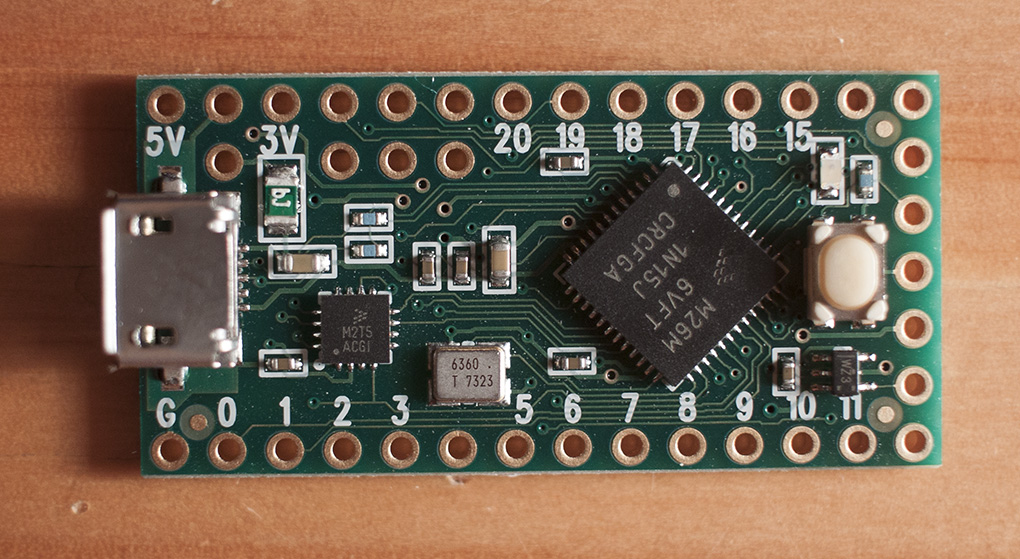
The festive season ’tis upon us and I have come bearing MIDI controller gifts. A while ago I was searching the internet for Arduino projects I came across various MIDI controller projects and I thought they would make a good gift for my two brothers since they both write music on their computers. I’ve stumbled on the Teensy a couple of times in the past while looking at custom game controllers for the Retropie project I’ve been working on but I hadn’t realised that the Teensy can be programmed as a class-compliant USB MIDI interface meaning it is basically plug-n-play.
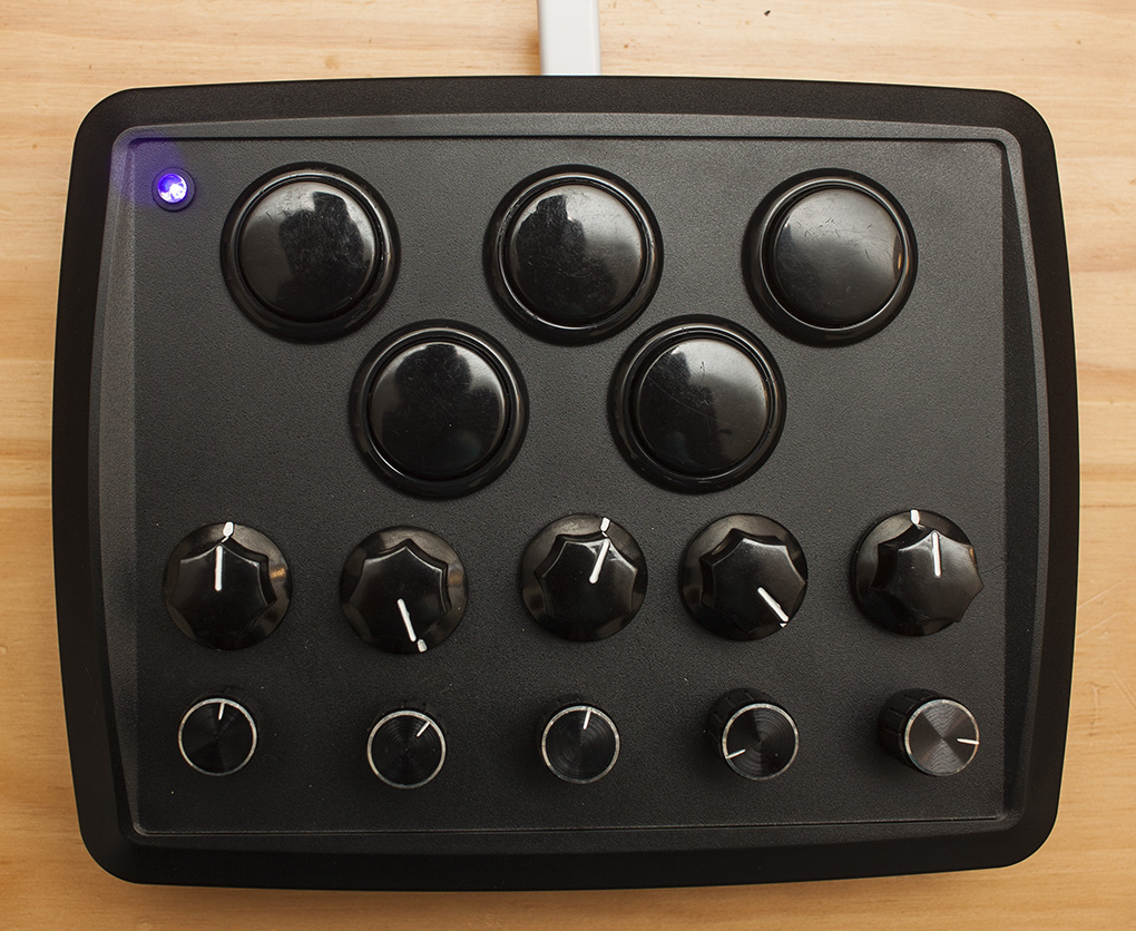
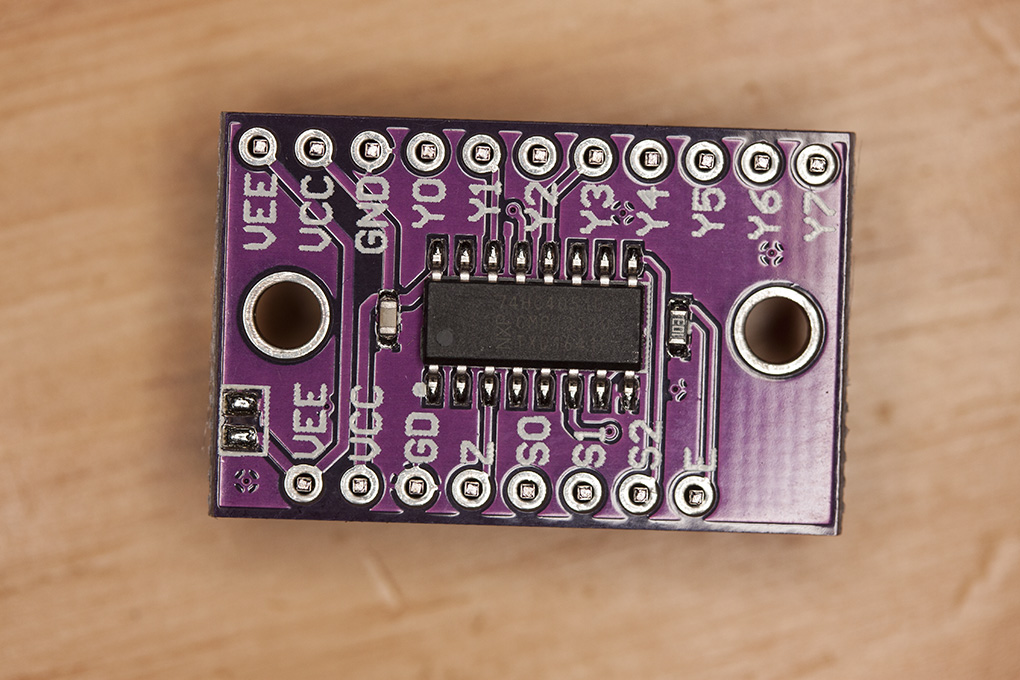
The plan was to make a reasonably portable controller. That way it can be balanced on an arm chair or held in one hand if desired. For this I decided on a fairly small, low profile box which would house five large push buttons, five rotary encoders with push buttons built in and five potentiometers. The standard Teensy LC inputs would just about cover my requirements but I wanted to make sure there was some spare in case I use the design for a controller for myself where I may add more controls so get more inputs I used an 8-way multiplexing chip, the 4051. It also has the benefit of being able to daisy-chain them and read many, many inputs on just a few pins . After a while tinkering on easyeda.com I came up with this…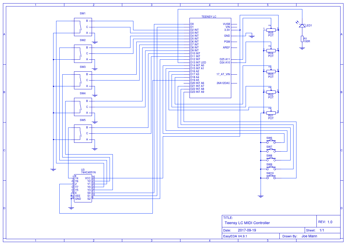 The 4051 can be used for digital or analogue and only uses four pins on the Teensy. Three are for sending control signals, one is to read back the data from one of the eight selected (in this case, input) pins. It works by raising the three control pins in different combinations. Three pins gives you enough unique combinations from a truth table to select one of eight pins. From that you can determine which of its eight inputs has been connected to the output pin and read the current state.
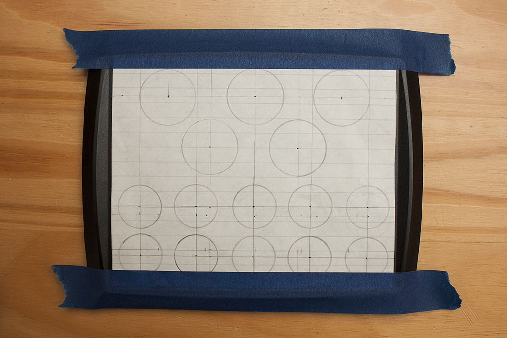
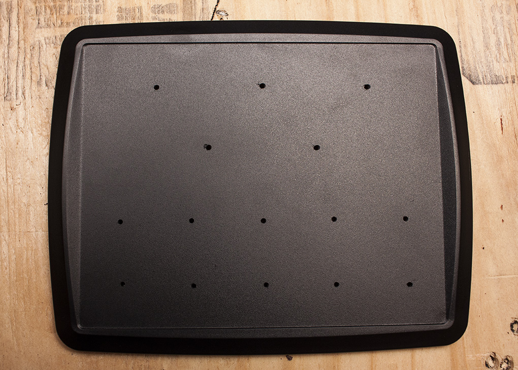
Before I could actually get busy with the soldering iron, I had to drill holes for all the controls in the box. I started off with a paper template that I had measured out all the controls on to and using a compass, pressed some small holes into the plastic which would act as a pilot hole for my pilot holes. Pilot hole inception?!
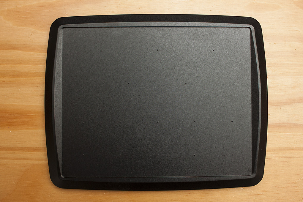
 The pots and encoders need 7mm holes and the large push buttons 30mm so steadily with a hole cutter and a 7mm bit I arrived at this.
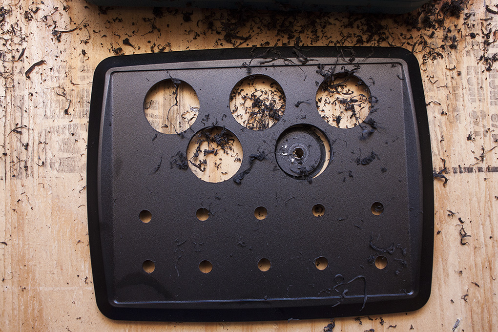
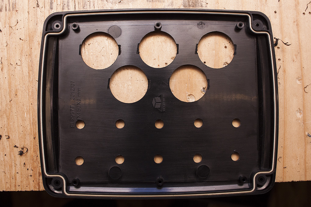
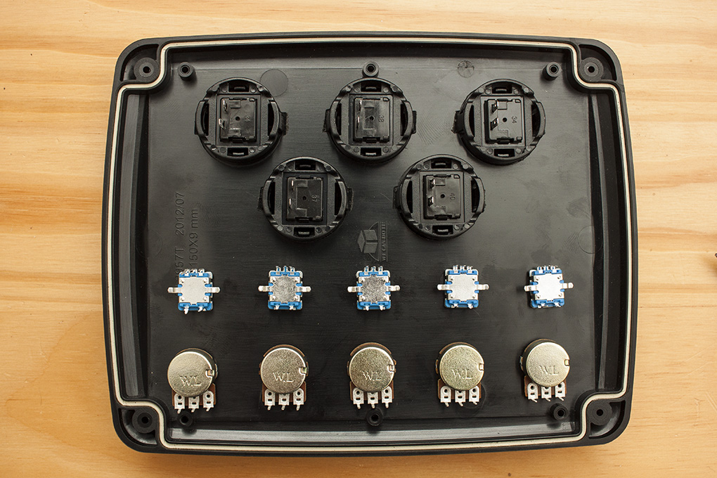
As the plastic is just slightly too thick for the push button clips to snap in I filed some chamfers in which held them in nicely and should also stop any rotation.
After fitting all the controls I was ready to start connecting everything up.
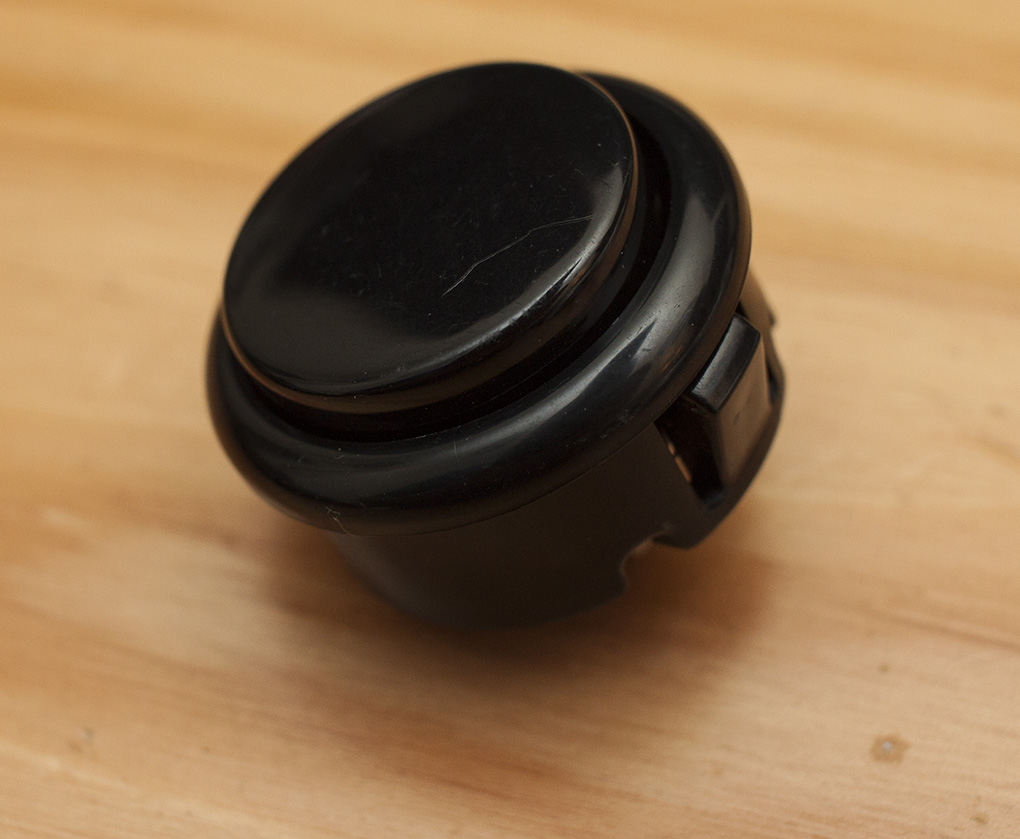
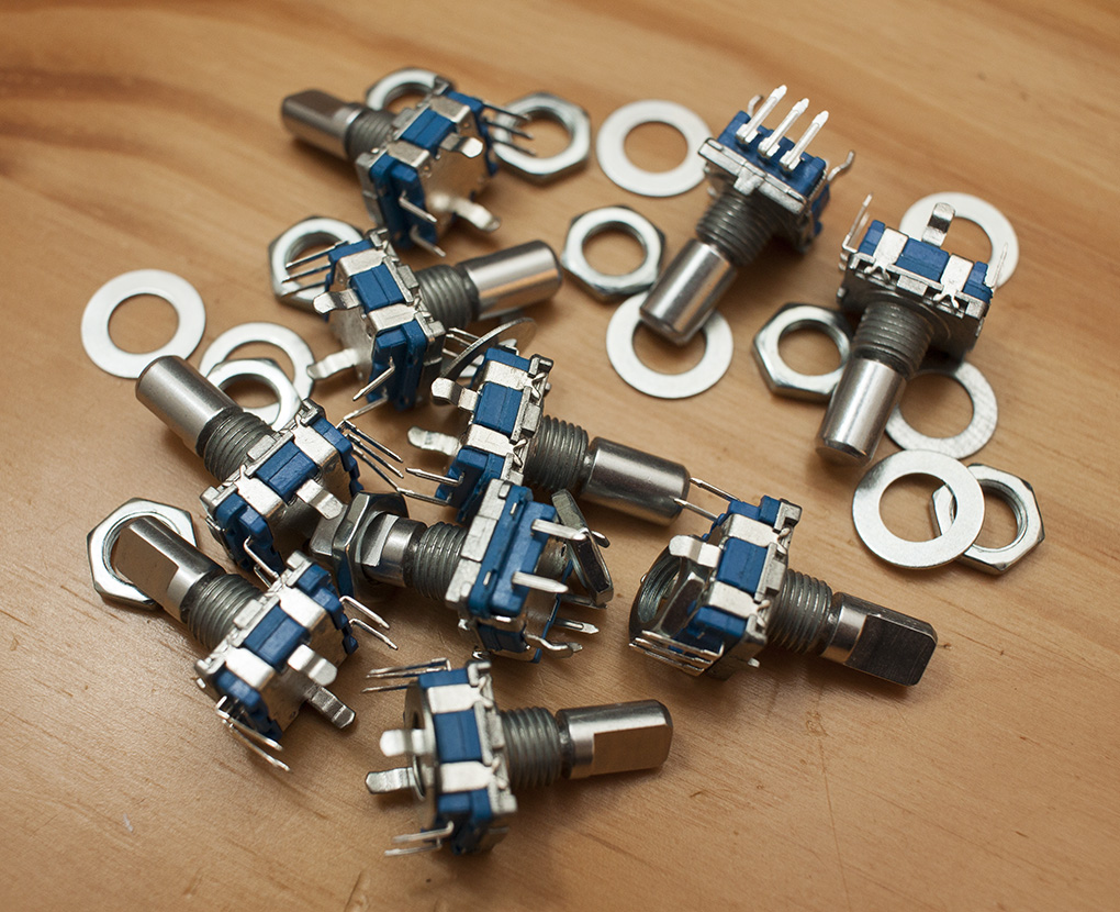
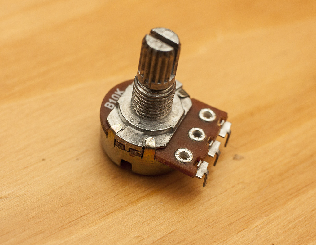
 All the controls were from China. They take a little while to arrive and I did have a couple of dodgy pots but on the whole they are perfectly fine for this and it keeps the total cost down to something reasonable.
Originally I had intended to use some strip board with the Teensy and multiplexing chip mounted on it with IDC connectors and ribbon cable but after wiring some of the inputs in I had no end of troubles trying to read signals. Some of this I addressed in the code such as making sure digital inputs had the pull-up resistors enabled and used a de-bouncing button library. The IDC connectors were just too unreliable though and I was getting some very jittery readings from the analogue pins.
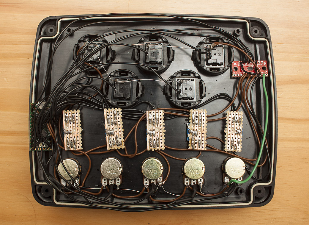
I desoldered everything and started again. This time adding some strip board to the encoders to save the pins getting bent (and in some cases breaking off). I soldered all the connections directly into the two boards too. I also used some mux chips mounted on a breakout board (actually I ended up with two slightly different ones but identical in function). I grounded one side of all the buttons, potentiometers and the centre pin of each rotary encoder as the Teensy is waiting for a low signal on each digital input. The other side of the pots is connected to 3v and the wiper is connected to the analogue input pins.
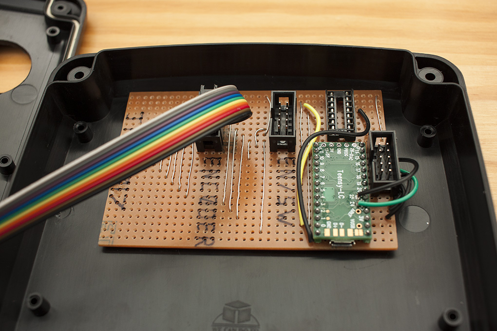
Below is part way through soldering and I’ve got a ground wire running round to all the controls. The casing of the encoders, one side of the switch and the center pin are all commoned together on the strip board which is also connected to one side of the pots and the large push buttons.
Now the wiring side was finished it needed programming. I’d already got some basic code ready for it as I’d been messing around with bits of breadboard and stuff to work out how all the inputs would work. After a ton of of reading and testing I ended up with this.
I’m using the Bounce object for the main buttons which is excellent. The inputs on the main buttons have the pull-up resistors enabled also to stop any signals floating around. This basically connects the input to 3.3v via a resistor, when you press a button the input is grounded to 0v which is what we look for (counterintuitive, yep!). The bounce library deals with looking for the falling edge of that signal to determine if the button has been pressed. This sends the MIDI note “on” command for that button while indexing into an array of notes, one for each button. It’s also looking for a rising edge on the signal to send the MIDI note “off” command for that button when it’s been released.
For the rotary encoders I’m comparing the last value read with the current one to see if it’s changed and constrain the value between 0 and 127 to suit the 8-bit value required by MIDI. The encoder itself is read using another excellent library that is available on the Teensy. That deals with reading a quadrature encoder very well and is simple to use. The only slight issue with this is with the initial value. For example, I’ve opened Ableton and assigned an encoder to one of the controls in the software. As soon as I start turning the encoder, the value in the software jumps from what it was to the first value read from the encoder when which is going to be somewhere around zero. There’s not a lot I can do about that because I don’t know what the starting value of an encoder control should be until it has been assigned to a control in the software. At that point I would also need to read the value from that software control and write it to the encoder object before the encoder is rotated! Still, it’s only a minor inconvenience. Once you’ve assigned all the encoders and used each one for the first time, all those values are stored for that session.
The analogue inputs on the Teensy have 10-bit resolution but this is also constrained to 8-bit from the pots for MIDI purposes. The last value and the current value are compared to see if a change of more than 1 has occurred. This is because some resolution is lost in the conversion from 10-bit to 8-bit and the input can teeter between two converted values. I also found the pots very sensitive to good grounding (no surprise with analogue) and had to swap a couple out that didn’t perform too well. I have a similar issue to the encoders with the initial values on the pots when they are assigned but unlike the encoders, the analogue inputs are constrained by what position the pot is in before you have assigned it.
The last part of the code deals with the 4051 multiplexing chip. This works in a similar way to the other controls in that the previous value and current value are compared to see if there’s been a change. This comparison only occurs when a minimum of 5 milliseconds has elapsed since the value last changed which is basically de-bouncing the input. I had some pretty odd oscillation going on with the encoder buttons until I added a 10 microsecond delay between raising or lowering the selection pins on the chip. I found that this just gives the chip a chance to switch channels before the input is read. It’s behaviour that I only saw on one controller for some reason. Could be because it’s a different chip manufacturer possibly.
That’s about it really. It’s been difficult at times trying to figure out why I’m not getting the signals I expected but it’s a really cool project to have finished. I’m well impressed with the power and robustness of the little Teensy board as well as all the libraries that go with it. I’m pretty certain I’ll be building my own MIDI controller some time in the near future with all the spare parts I have left over.
One last thing. Chris, pins 19 and 21 are swapped over on yours so keep your eyes peeled for the alternative schematic and code on easyeda.com and github.com.
One thought on “Teensy LC USB MIDI Controller”
Nice work!! I love building MIDI encoders using Teensy’s. FYI, below is some good code if you want to make your encoders relative rather than absolute for avoiding the initial jump-to-value problem when using with Ableton. The code uses Ableton Relative signed bit.
https://github.com/squarefrog/teensy-midi-encoder-box