I originally stripped the whole engine nearly 4 years ago. The main caps and big ends/conrods were already numbered so I think it may have had new big end and main bearings or something at some stage. The pistons look like the original ones as they are stamped with “Stanpart”. I knew the big end was on the way out again though because you could hear it on cold mornings. I wanted to do some work on the short engine for a bit more power since I’ve already worked on the cylinder head and also try and improve the oil feed in the bottom end.
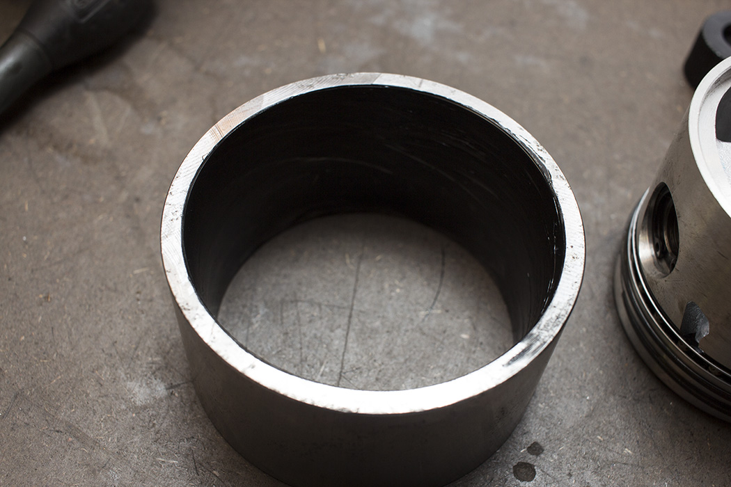
When I originally stripped it down my dad helped me measure the cylinder bores for roundness and taper. At the time we decided it was okay to keep the bores as they were and just deglaze them. Problem is that was a long time ago and I couldn’t remember exactly what we had measured so I bought myself a micrometer and dial bore gauge. I zeroed the dial bore gauge to 73.66mm (2.900″, nominal bore size according to the manual) using the micrometer, took various measurements several times and calculated bore roundness and taper. I posted on the forums for advice and checked the books. The max out-of-round or taper is 0.154mm (0.006″) and I was well within this.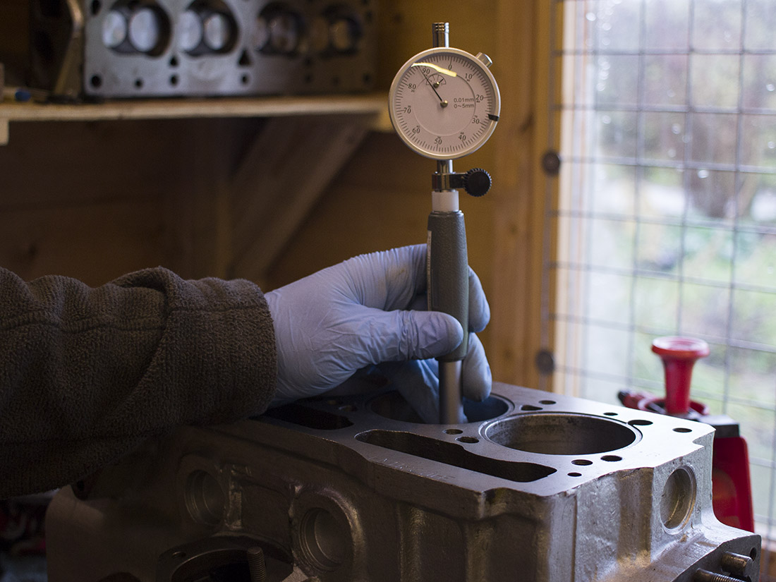
Typical measurements…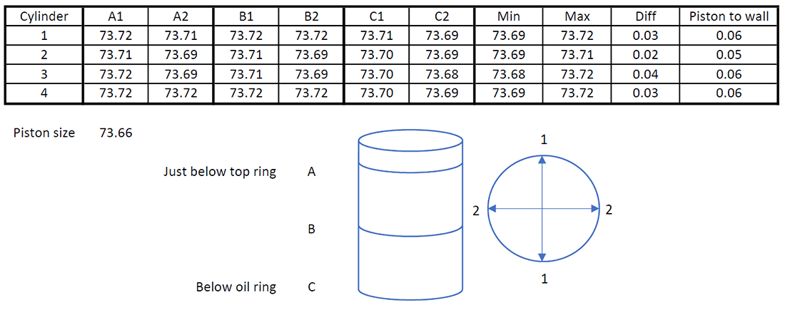
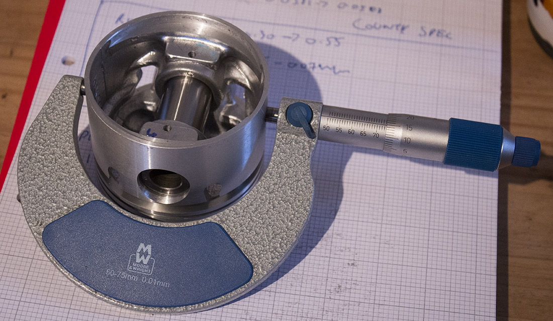
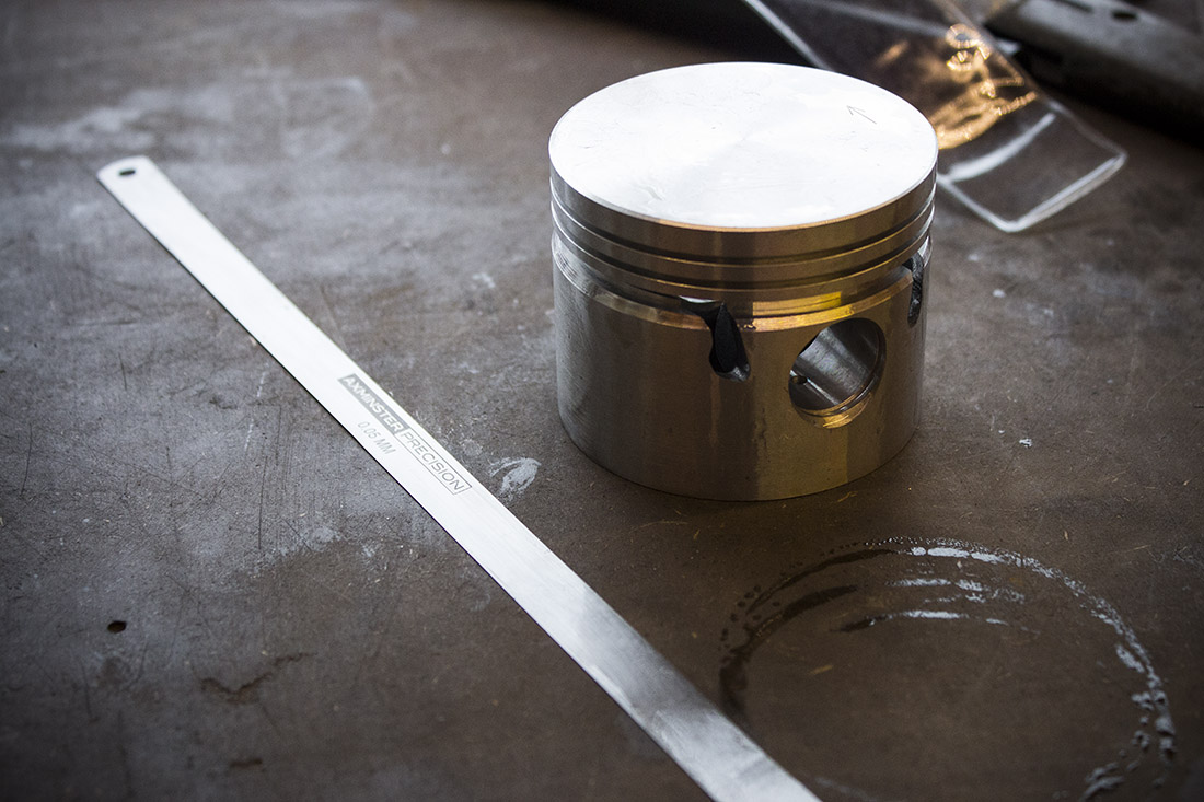
Now I was confident that the bores were in tolerance, I wanted to check that the pistons were too. These measured up to 73.66mm ±0.01mm. This would mean they are on the limit of the tolerance specified by the book. Just to be sure they would be okay I used two long 0.05mm and 0.07mm feeler gauges in each bore and assigned a piston to a cylinder for best fit. The feeler gauge method seemed a bit crude but OK to confirm my measurements for peace of mind. I found them all to be somewhere between 0.05mm and 0.07mm which is what I had measured with the dial bore gauge. In fact I couldn’t get the 0.07mm feeler gauge down any of the bores so now I knew the pistons were suitable.
The rings also needed measuring for gap clearance at the bottom of the bore where it’s slightly less worn. There is a general rule of thumb that the ring gaps should be about 0.004″ multiplied by bore diameter as a minimum to allow for ring expansion. In my case that’s 0.0116″ (0.29mm). In some cases I have as much as 0.5mm which is actually out of spec according to the ring manufacturer although in spec according to the workshop manual. After some research I’m not too bothered about that though. This article from the Institute of Diagnostic Engineers explains why and makes some interesting points about ring gaps and offsetting gaps when installing pistons. The basic theory being that the ring gap is such a small proportion of the total area being sealed that it doesn’t make a significant difference in blow-by or oil consumption. Especially when you consider that there are two compression rings—that totals over 18″ of ring to wall contact for my engine. What seems more important is ring groove clearance and radial thickness of the ring as those are what determine good ring seal. Both fine on my brand new piston set.
I had already weight matched the conrods some time ago. I matched all the big ends by removing material from the rod caps and total weight by removing material towards the small ends. It’s pretty tricky to get accurate readings on the scales when comparing big ends but I found that an old gudgeon pin in the vice with plenty of oil on it helped keep each rod in the same position over the scales. I also removed casting marks and rough edges from the I beams and polished them a little to reduce stress risers. I also checked the new gudgeon pins for fit which should need a bit of a push to get them through but they shouldn’t drop through under their own weight. Mine were fine.
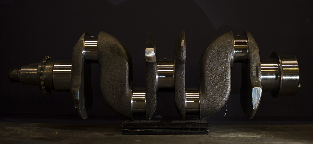
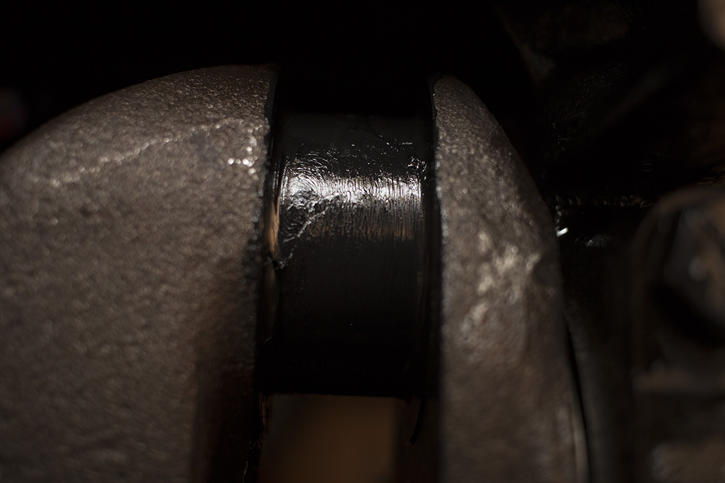
The major part of the balancing was done on the entire rotating assembly which includes the crank, crank pulley, cam chain sprocket, flywheel and clutch. All this had to be done by a specialist machine shop, Jigsaw Racing. I had the journals ground and polished to 0.010″ along with new bearings supplied at the same time. Much of the material for balancing was removed from the counterweights and webs on the crank but there was a few other areas such as the outside of the clutch pressure plate and the flywheel itself. While they had the flywheel it had a new ring gear and was refaced.

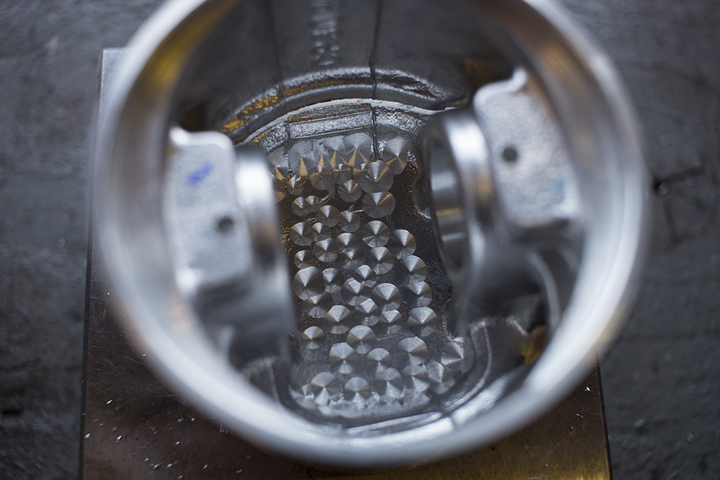
Next up was to complete the balancing by weight matching the pistons. After measuring all 4 pistons and gudgeon pins I found that the gudgeon pins were already within 0.1 gram which is beyond the accuracy of my scales anyway. Two piston and gudgeon pin pairs matched up within 0.1g so I just had about 1.5g to remove from each of the other two. I did this by removing material from the underside of the piston crown. I kept the distribution of holes as even as possible and the depth to a minimum so the crown wasn’t weakened too much.
A little work on the oil pump was needed. After some research I decided to use the older style straight pickup. The later angled type actually points towards the rear of the sump so it can easily be starved under braking (not sure how that was meant to be an improvement?). Making a baffle to fit around the straight pickup would be much easier too. I needed to make sure the mating face was flat by sanding it on 1200 grit paper on top of a piece of ground flat steel. This would ensure the pump is within tolerance and working efficiently. As you can see below, it was a bit rough out the box.

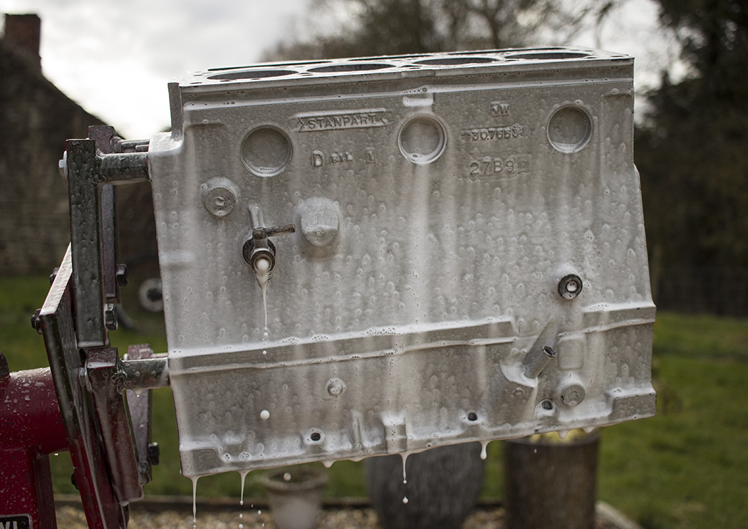
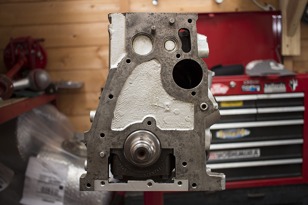
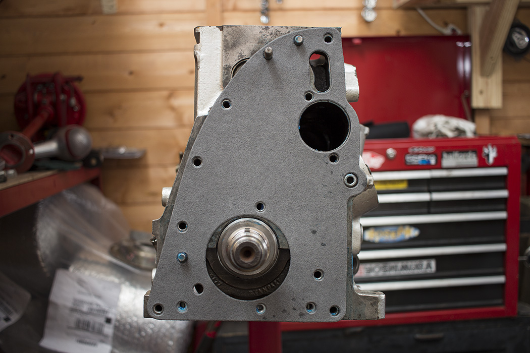
Two things left for the block before cleaning it and fitting all the parts. Firstly the guys in the machine shop at work ground the top of the block flat for me. The 40 year old finish on the top isn’t the best. This should mean a good seal between the block and the head since both have been ground flat. I also drilled out the centre main oil feed to 5/16″. Opinion on this being beneficial is divided but it makes sense to me. That centre main feeds the centre main bearing and two big ends but is drilled to the same size as the other two at the factory. The oil pump should have plenty of capacity to maintain pressure with the increased flow in this area so it should be beneficial. British Leyland engineers of the day used this method for race preparation so it’s good enough for me. I just used a long 5/16″ bit, drilled from the centre main housing and then from outside behind the distributor bush which can be knocked out with a brass drift or similar.
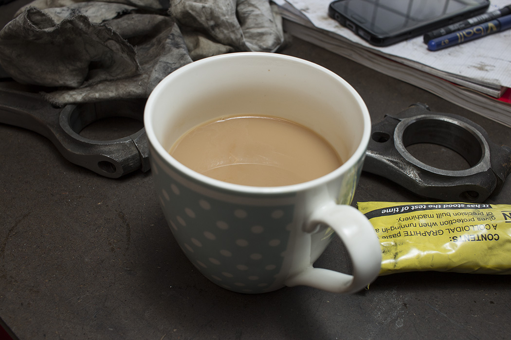
Now everything was about ready to install in the engine. I had all the components I needed. I gave the block and crank a final degrease and wash before thoroughly drying with compressed air. I applied graphogen assembly paste to the cylinder walls, camshaft journals, follower bores etc. It can be used on pretty much any surface and doesn’t run off so it’s ideal for my build since it’s going to be some time before I crank the engine up. Once the engine is running and oil is flowing the graphogen dissolves in the oil.
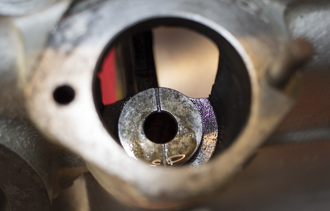
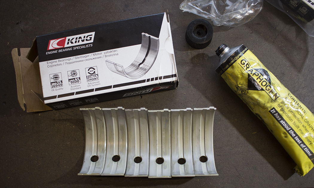
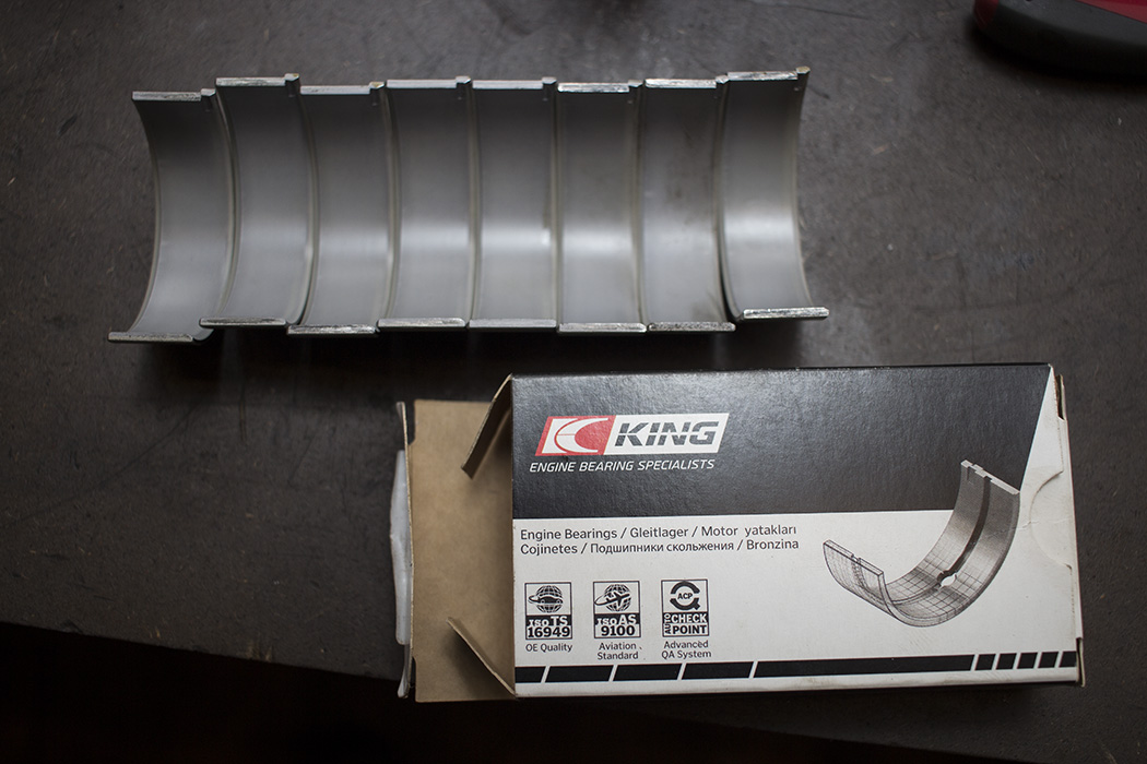
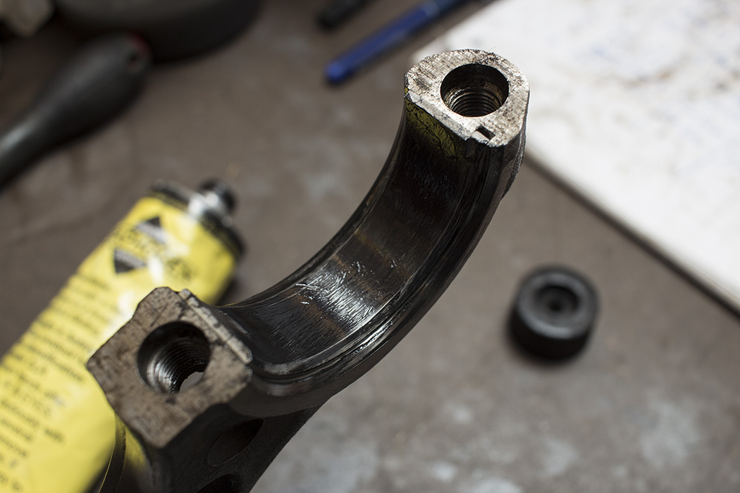
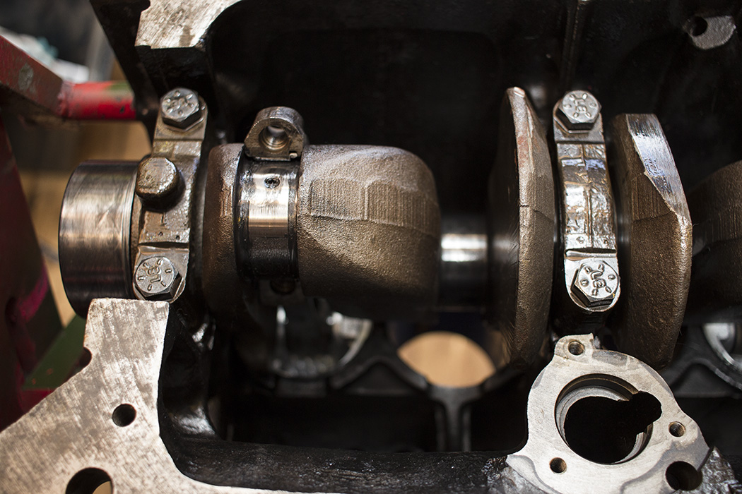
Now the block was clean I just had to knock the distributor drive bush back in since it was removed to open up the oil gallery. I marked this before it was removed to make sure I put it back in the right way. I think this is just to align the oil feed up though I don’t think it’s critical. After that it was ready to fit the crank—I cleaned up the main bearing caps and reminded myself of the orientation that they go in. On this engine the tang on each bearing shell goes on the same side, that way you can’t get the caps on back to front. The order of the caps was easy since they were already marked one, two and three. One being closest to the front of the engine where the crank pulley fits. Jigsaw Racing supplied King tri-metal shells which I understand to be very good. They also supplied thrust washers, one standard and one oversized (0.010″ if I remember correctly). I was hoping that resulted in the end-float being within tolerance.
A cap with bearing shell installed ready to fit…
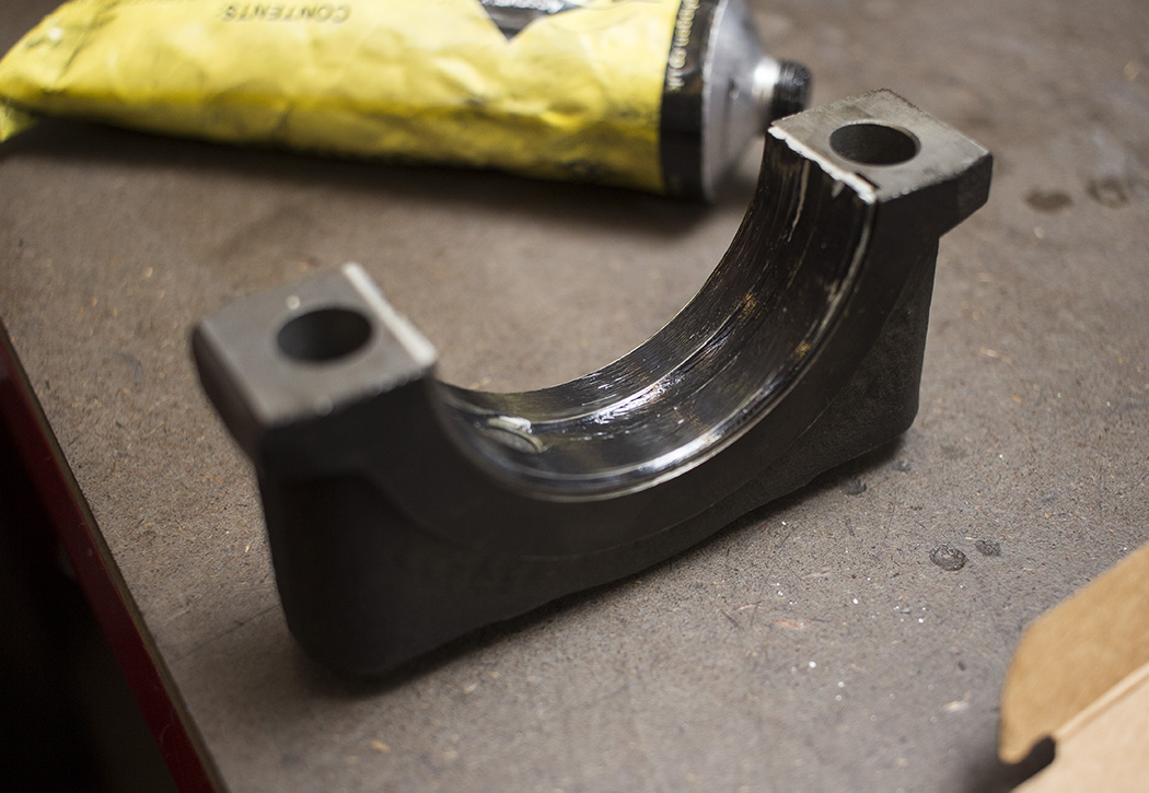
The graphogen actually works quite well when installing the thrust washers as it helps keep them in place as well as lubricate them.
Three shells and two thrust washers were now installed in the block and they all had a fairly generous application of graphogen. I cleaned the main journals of the crank and checked that all the oil ways were clear before lowering it in to place.

I had new uprated bearing cap bolts ready to install so I made sure they were cleaned and applied a little oil. I know lubricant can affect the affect the clamp force of a fastener for a given torque but since the threads were bone dry I thought it would be better to have a bit of oil to prevent galling. The spec on the 1500 is 65 lb/ft (88Nm). I torqued the caps up starting with the middle one and progressively doing all six bolts. I don’t really know if they need to be done progressively but I didn’t think it would hurt. The crank spun with one hand, just with a little resistance so that was reassuring. I checked the end-float and that was pretty good. The end-float tolerance is 0.102-0.203mm, mine came in at 0.1mm so I was very chuffed with that.
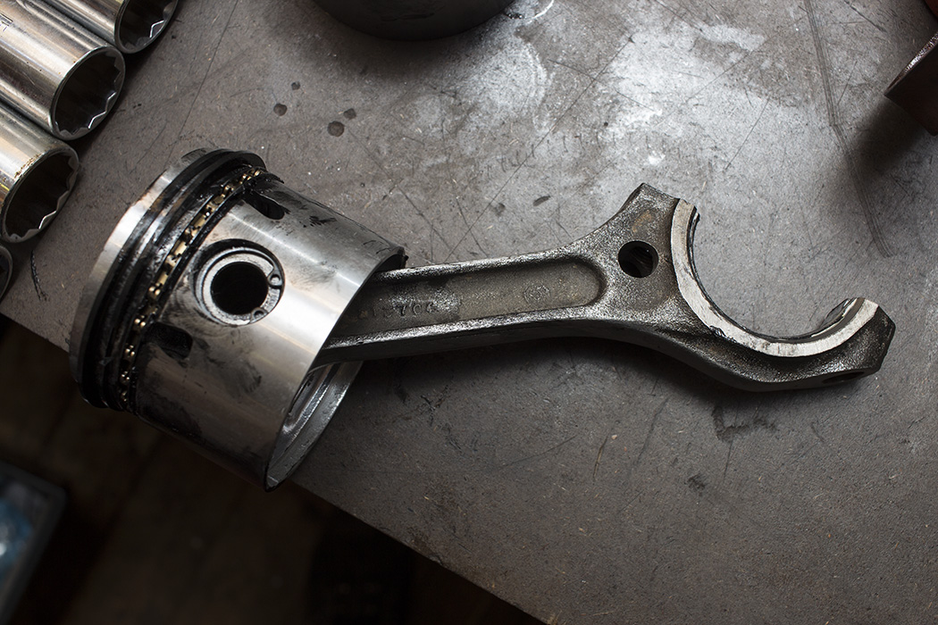
So the crank went in beautifully. Next up was pistons and rods. A good clean followed by putting the rods on the correct way which I didn’t manage to do the first time round. Easily done when the engine is upside down. The clearance is very tight. Install them the wrong way round and I would imagine a rod trying to make a swift exit through the side of the engine casing. I had already decided which piston to assign to which bore based on size so it was just a case of matching them up with the rods.

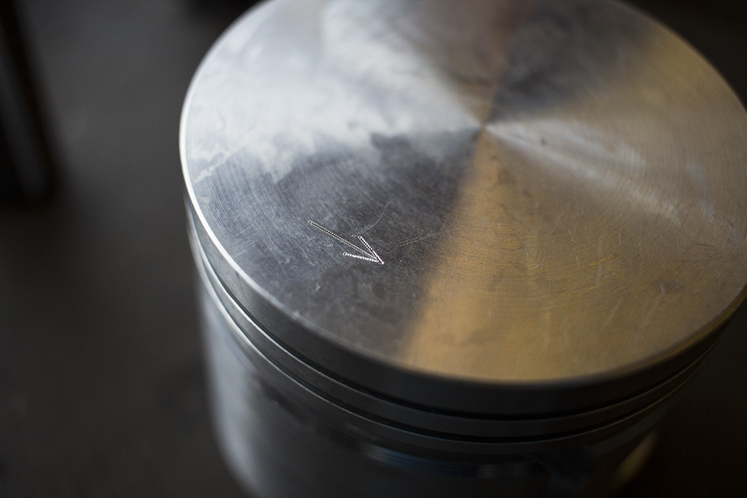
The pistons are marked with an arrow which should face the front of the engine. The bolt heads on the big ends should be facing the side of the block towards the camshaft.
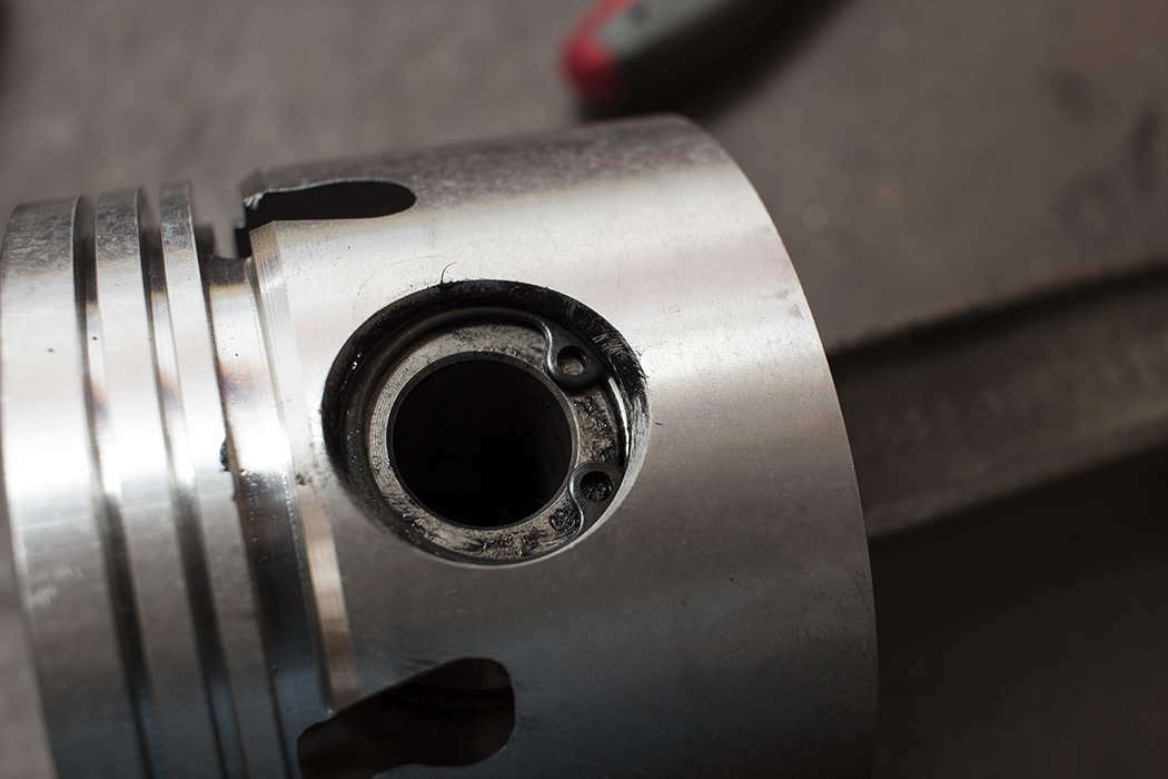
 I made sure the gudgeon pins had a good coating of graphogen on them and installed the circlips making sure they had seated well.
 Now it was time to install the rings from the bottom oil ring up. Oil ring spacer goes on first. In my case they had a different colour on each end. This is to make it easier to see that you have the ends butted up to each other and they aren’t overlapping. I found it a bit tricky to stop them overlapping but it’s easy enough to push them in to position afterwards. The lower oil ring followed by the top oil ring can go in. They just slot in to the oil spacer which can be tricky but I managed by holding the rings at the ends and carefully pushing it outwards. The oil ring is quite delicate.
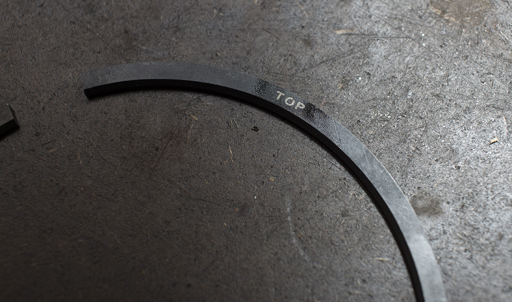
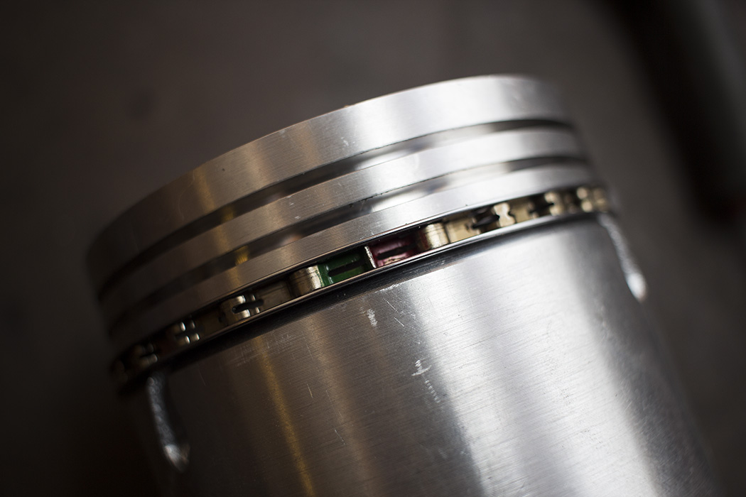 The second ring and top ring are both marked so you know which way is up. They are a lot thicker and tend to be a bit easier to jostle in to position. I couldn’t actually tell you the difference between the second and top rings but they come in a marked plastic bag so you know which are which.
 Now for a crucial part of any engine build…
 King tri-metal bearings were supplied for the big end. Installation was pretty straight forward. Just snap one in to the rod side and give it a good coat of graphogen.
Ignoring the fact I had removed it once to get the conrod on the right way round (good job it was just the first one). Here’s a photo of a piston and rod ready to go in. I applied some graphogen on the crankpins just for good measure.
The piston ring compressor I used was actually brilliant. A chap at work had machined a tapered ring to fit the pistons on his Mini project. It just so happened that they are almost identical in diameter to mine. A liberal coating of graphogen inside and they went in really easily with a few gentle taps from a rubber mallet.
 I installed the pistons in pairs, first 1 and 4, then 2 and 3. I had new rod bolts ready to fit and installed them with some Loctite according to the manufacturer’s spec. The manual specifies 46lb/ft (61Nm) or 50lb/ft (68Nm) depending on the finish of the bolt so I just opted for 46lb/ft since that spec would be for dry threads. Below is cylinder No. 4 ready for the big end cap to be installed complete with bearing shell and graphogen.
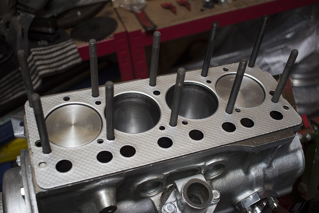
 Four pistons in. Ready to go…
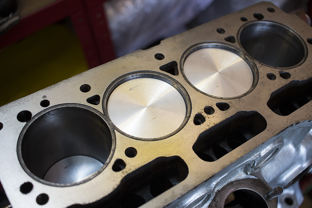
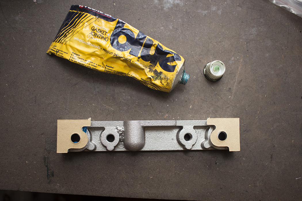
So that was it for the pistons. Facing the front of the engine I could rotate it with the crank pulley by hand without too much trouble so I would say that was a success. I just needed to install the sealing block that is located above No. 1 main cap. I cleaned up the original ready to fit but discovered it was pretty bent. I think this is a common area for oil leaks to start occurring so people tend to just crank the bolts up a bit tighter to try and stop the leak but it just ends up deforming the sealing block and making things worse. I ordered a replacement which is made from a much lighter alloy. It’ll be fine although it isn’t the precision machined replacement I was hoping for at a cost of £35!
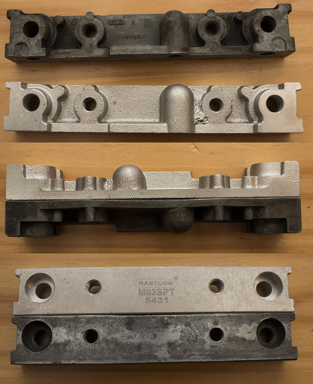
First I stuck the gaskets on with some instant gasket and applied plenty to where it would sit in the block. The sealing block is installed with Pozi-drive screws which makes it tricky to tighten them and they also have a tendency to get chewed up.

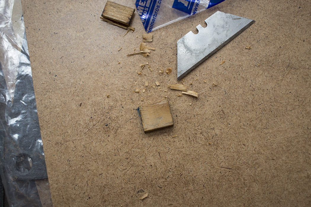
The two ends of the sealing block are sealed with wooden packing pieces. They come oversized for you to cut down to shape. That in itself is a little tricky and I managed to break one when knocking it in so I had to make another one from a bit of of pallet I had. Once they are knocked in with liberal amounts of instant gasket, the ends are trimmed off flush with the sump mating face.

Once that was done I cleaned up the mating face of the block, installed the gasket with some Hylomar Blue and then the engine plate.

I bolted the engine plate on for the time being so the instant gasket makes a good seal. I needed to paint the timing cover and I knew it would be a while before that was bolted on since I needed to install the cam and timing gears. The camshaft is a MK-III profile ground on to a large journal cam to fit the 1500. It has the same lift but has just a bit more duration on inlet and exhaust, 270° vs 256° on the stock 1500. I may consider roller rockers with a bit more lift ratio in the future but this cam is supposed to be pretty good compared to the standard 1500 one.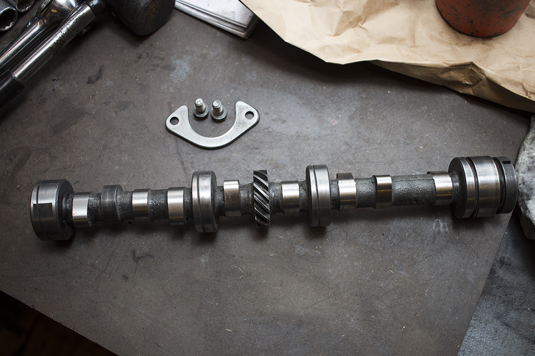 More graphogen on all the lobes and journals as well as in the block. The cam was pretty easy to install and can be steadied through the distributor drive hole.
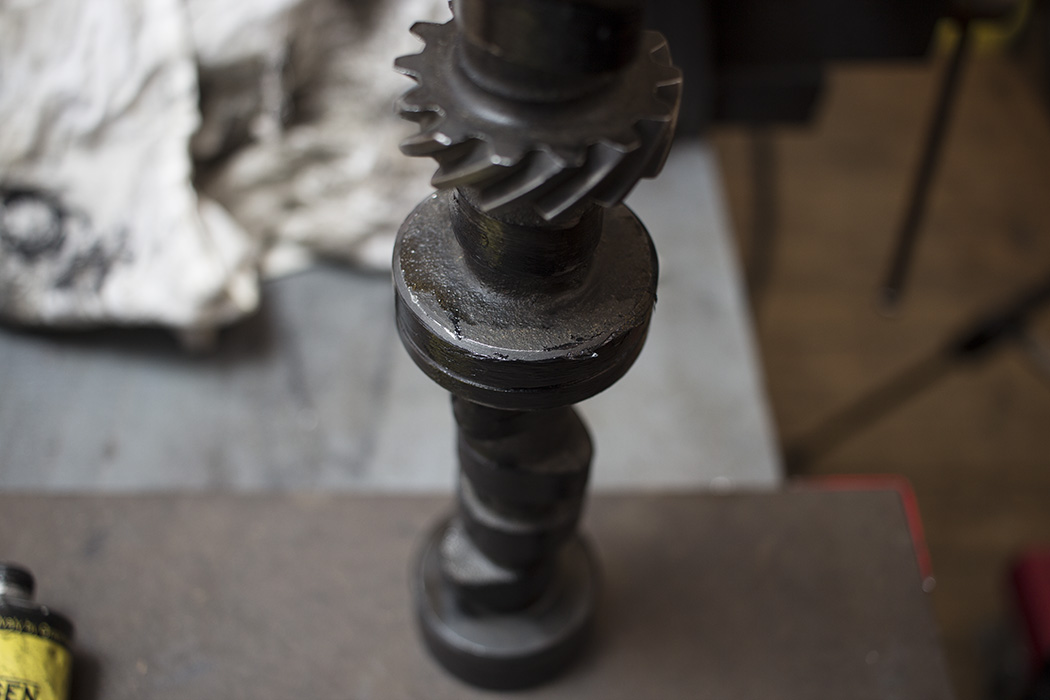 The longer bolt in the end of the cam just helps to get some leverage on it and keep it level as you install it.
 I installed the retaining plate next but found that the cam wouldn’t turn at all with it tightened up. I measured the gap on the cam, 4.66mm. The width of the retaining plate was 4.62mm and the specs call for 0.10-0.20mm end float which I think is to account for the distributor drive gear clearance more than anything. Thankfully the chaps in the machine shop at work could help me with that one and machined the plate down to 4.40mm. This is actually slightly out of spec but the plate doesn’t stay perfectly flat once it’s tightened. Maybe that could be improved by fettling with the engine plate but getting that perfectly flat didn’t seem worth it so it was easier to have the cam retainer machined to tolerance which would also remove wear from the previous cam.
After it was machined I re-installed it and checked the end-float on the camshaft using a dial gauge. I found that the plate became more distorted as the bolts were tightened which resulted in end-float getting smaller and smaller. I decided to put a bit of Loctite on the bolts as well as locking washers just to be sure they wouldn’t come loose and tighten them until the end-float was just over 0.1mm. The bolts were pretty tight at this stage anyway and since there doesn’t appear to be a torque spec for them in the book, that would have to do.
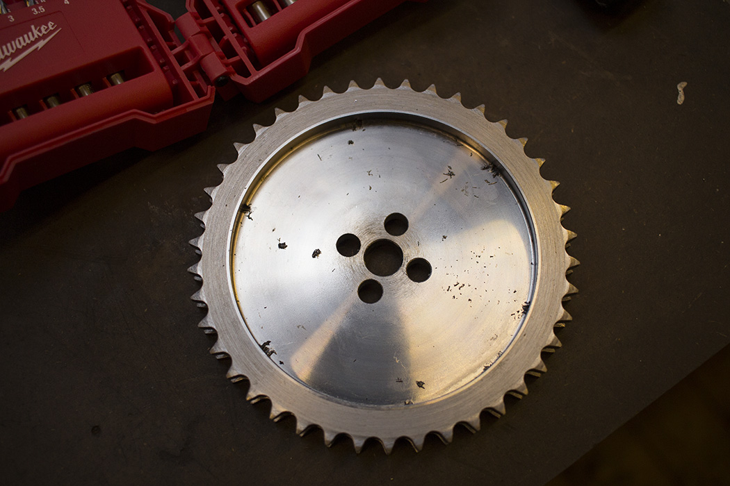
 I decided to fit a dual row chain and sprocket set on my engine which should be more reliable, especially if I decide to fit higher ratio roller rockers later on. I couldn’t quite stretch to a vernier sprocket. The only minor drawback of the dual row is that you lose quarter-tooth adjustment for cam timing. There are four holes in the cam sprocket which are slightly offset. Rotating the sprocket a quarter of a turn gives you half a tooth of adjustment and flipping the original, single row over, gives you a quarter-tooth. You can’t flip the dual row version. Still, half a tooth of adjustment would be fine and if I had to I would advance the cam slightly in favour of low-end torque.
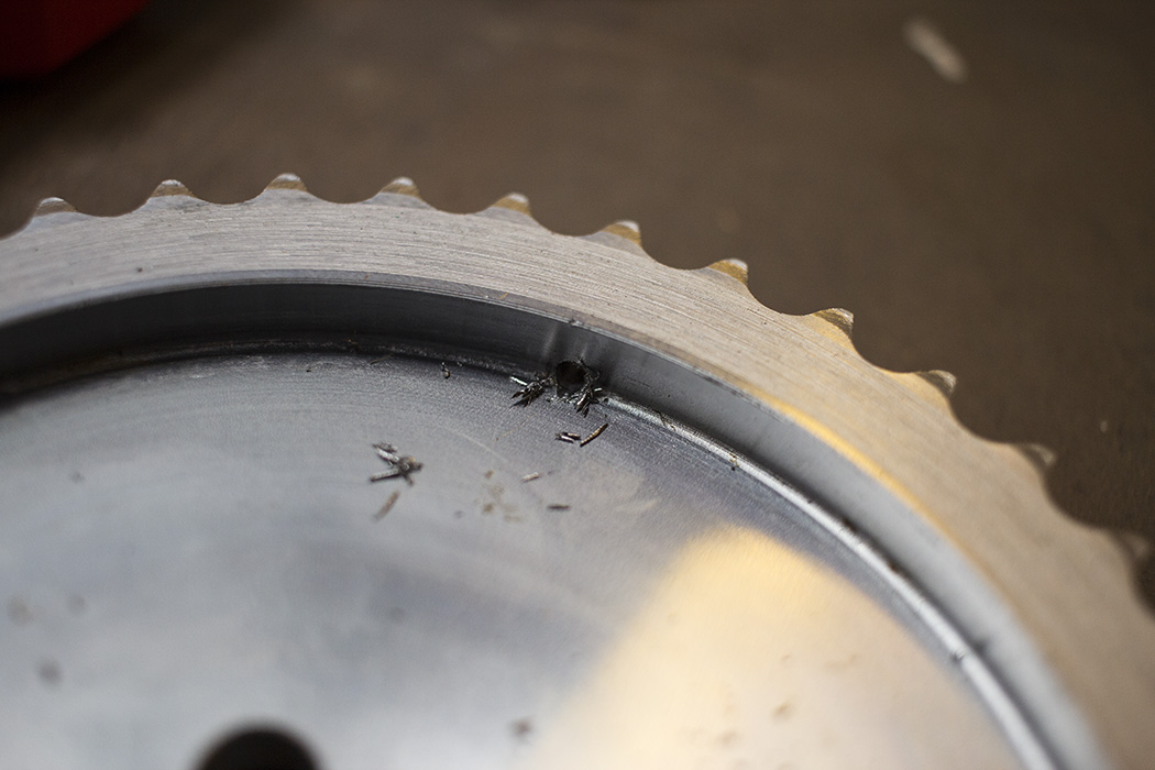
The dual row camshaft sprocket catches oil which exits the end of the cam after feeding the first journal and is distributed centrifugally to the chain via some small holes around the edge. These were full of swarf so I just ran the drill through them and cleaned them up.
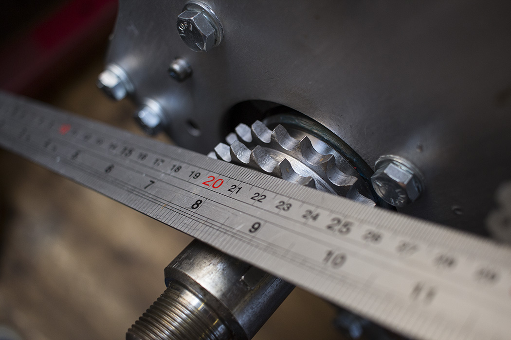
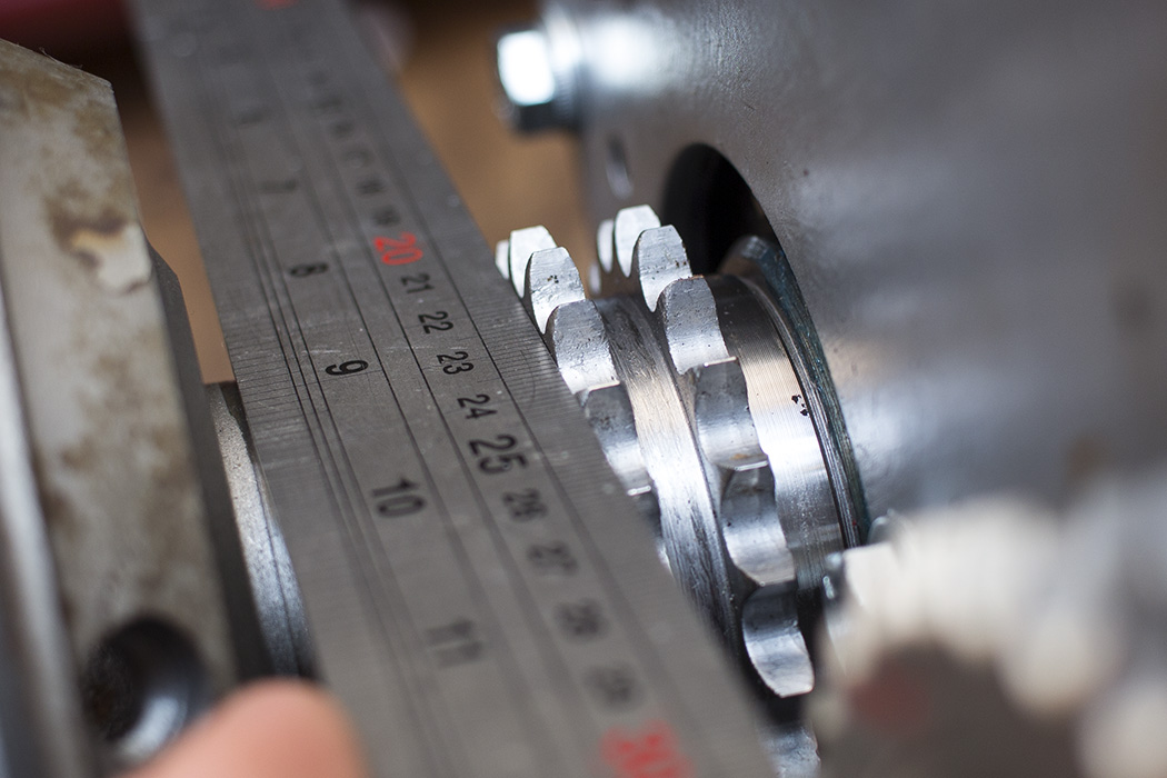
Now the camshaft sprocket was clean and the camshaft end-float was set, the sprocket could be bolted on temporarily to check alignment. I installed the crank sprocket at this stage too and checked alignment of both sprockets using a straight edge. The alignment is corrected by installing shim washers behind the crank sprocket. I had to install 6 shims, totalling 0.034″ (0.86mm). That was 4 more than fitted previously which I put down to gasket thickness, gasket sealant and paint on the engine plate.

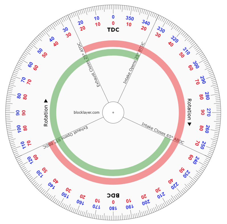
 Now the sprockets lined up I could get the camshaft timing setup. First of all I needed to make a degree wheel. Blocklayer.com has a good tool that lets you enter the cam details and produces a printable degree wheel.
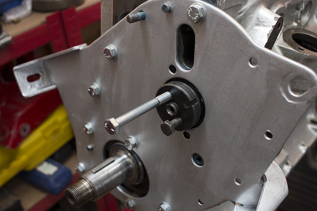
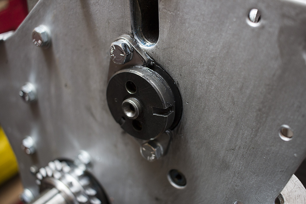
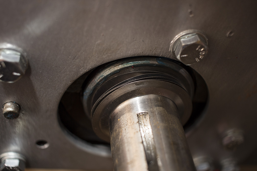
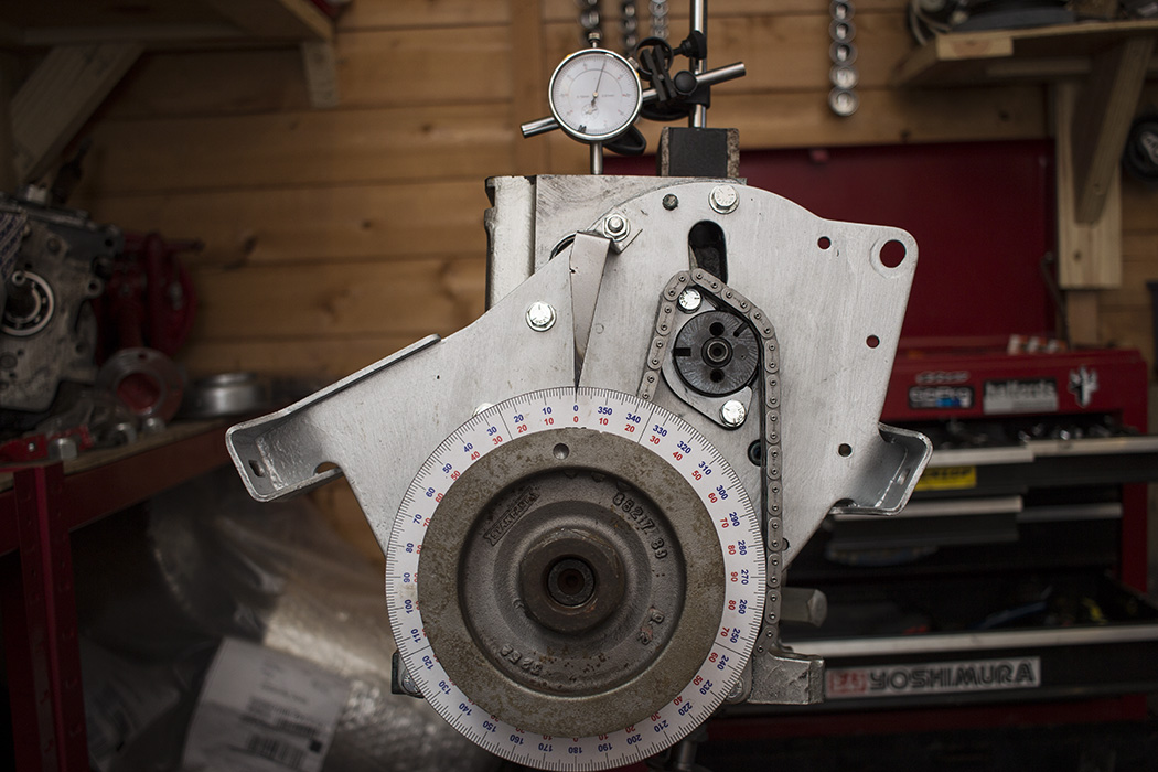
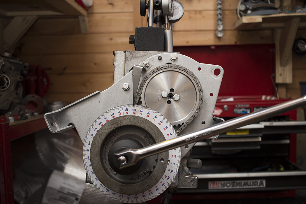
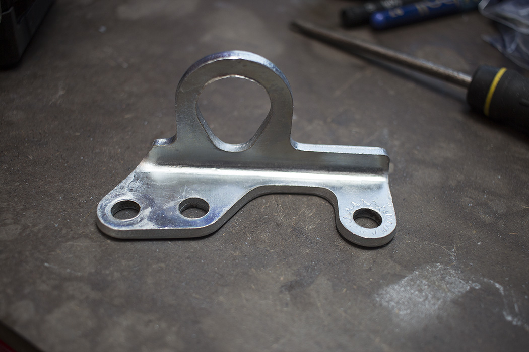
 Having made a pointer that bolts to the block I used a dial gauge and found true top dead centre. The woodruff key on the crank also points directly up at TDC. I fitted the chain over the crank sprocket followed by the timing disc, oil flinger, pulley and nut.
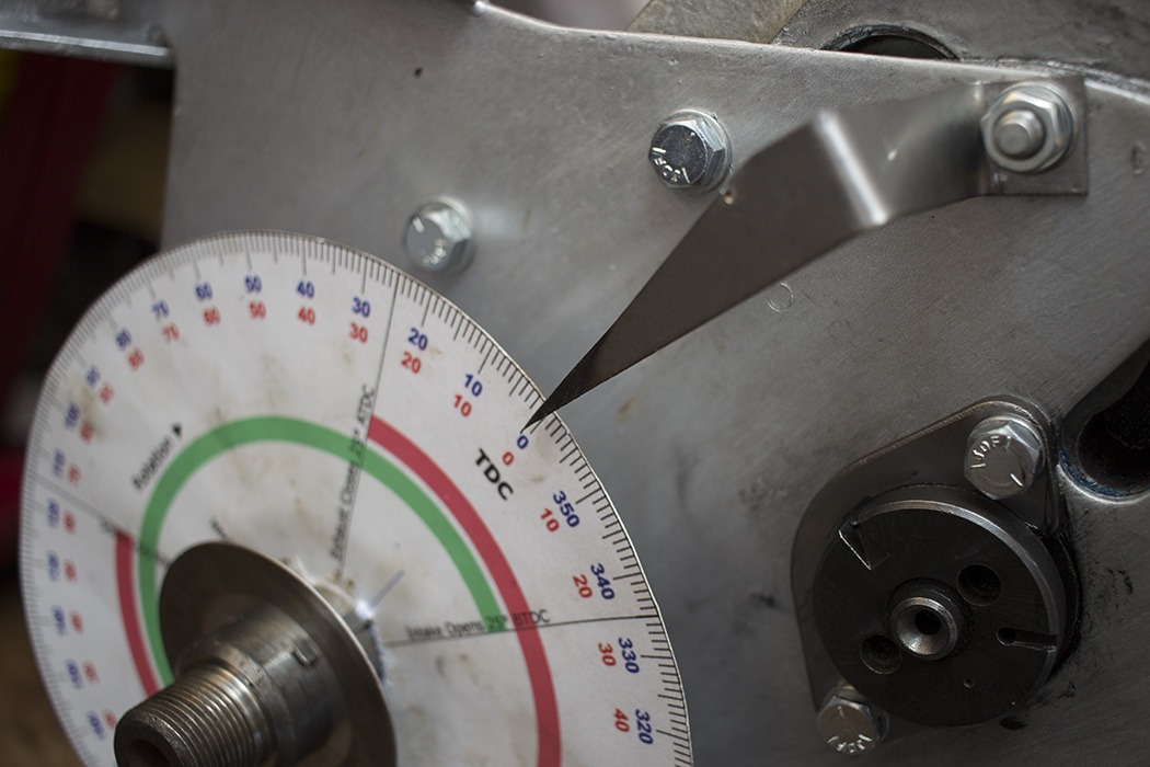
With the pointer roughly in the right place I could find true TDC and bend it slightly to get it correctly pointing at 0°.
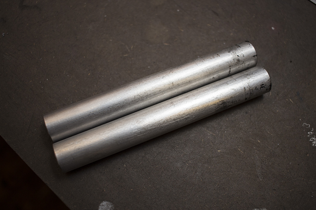
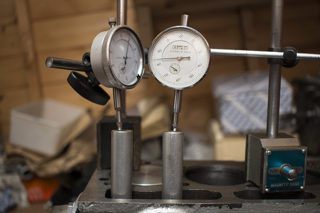
 The specs of the cam mean that the intake lobe peaks at 110° after top dead centre and the exhaust lobe peaks at 110° before top dead centre so I marked these up on the timing wheel and used them as the point of reference for degreeing the cam. With two evenly machined dowels to fit in the follower bores, I set up two dial gauges to verify that the intake and exhaust lobes peaked at the correct point. This could be done by checking just one lobe but I wanted to be 100% certain so I did both.
 Once I had the cam and crank in the correct position, I slid the cam sprocket back in to position and carefully rotated it within the chain one tooth at a time. If it didn’t look as though it would quite line up with the mounting holes I would rotate the sprocket 90° to gain or lose half a tooth of adjustment. This seemed to be enough to get it fairly accurate. Once it was bolted on I rotated the crank a few times to double check that the timing was still correct. I came across an issue though. I found that both the inlet and exhaust duration to be longer than the spec. The inlet on cylinder 1 was beginning to open about 35° before it was supposed to although it only opened about 0.010″ during that 35° phase. I did some digging and poked around on the forums where I came across “clearance ramps”. These are the initial part of the ramp which take up backlash in the valve train but don’t count towards the specified duration since the valve isn’t moving at this stage.
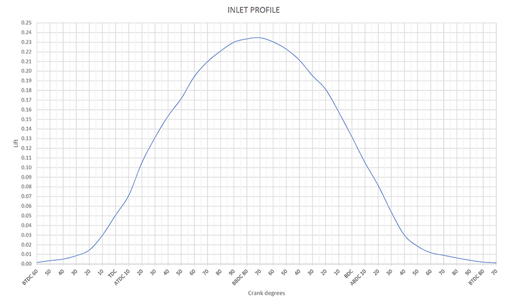
Here’s the profile of my cam. You can see where the the clearance ramps lead up to the specified opening, 25° BTDC at which point there is 0.010″ lift. The lift then rapidly increases and peaks at 110° ATDC before coming back down to roughly 0.010″ at 65° ABDC. The clearance ramp is very gradual so that lash is taken up relatively slowly.
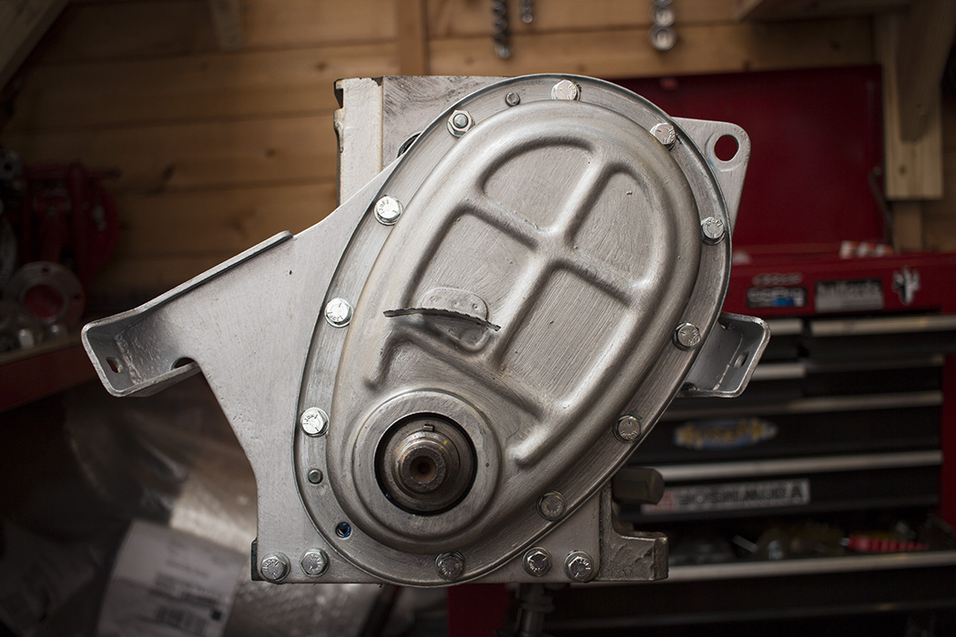
 Now the cam timing was sorted. I removed the degree wheel, installed the tab washer on the camshaft sprocket and torqued the bolts to 24lb/ft (32Nm). Then the cover went on which has a new oil seal and a wider spring tensioner to accommodate the duplex chain.

 Next up I installed the rear crank seal which is just about accessible behind the engine stand. Fairly standard procedure with gasket sealant, a new oil seal and new bolts.
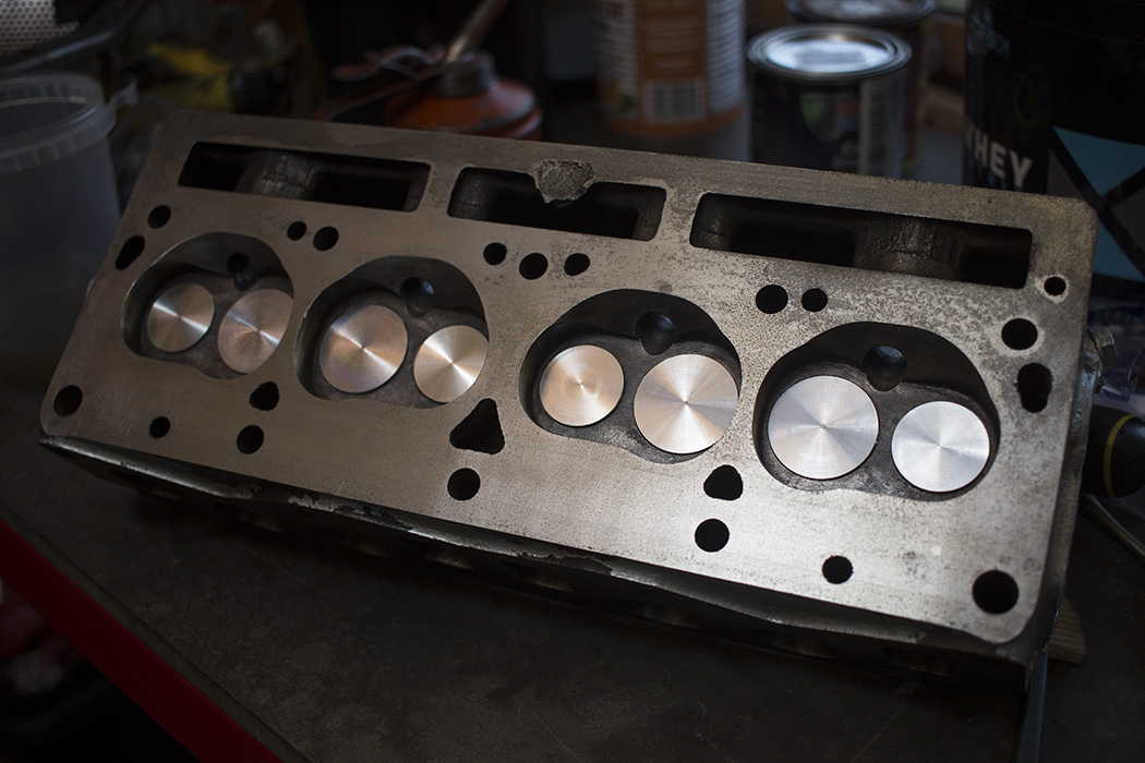
 Now the cylinder head was almost ready to install. I replaced all the head studs with new ones and installed a set of new cam followers with liberal graphogen.

 One final degrease and clean up of the block and cylinder head faces, then I installed the gasket and torqued the new nuts down to 46lb/ft (63Nm) in sequence starting from the middle. I also installed my freshly plated lifting eye that I’d just finished plating with my new zinc plating kit. Very happy with the results.
The ground finish on the head and block got a bit of surface rust over the time it was stored but nothing that would affect the finish too much.
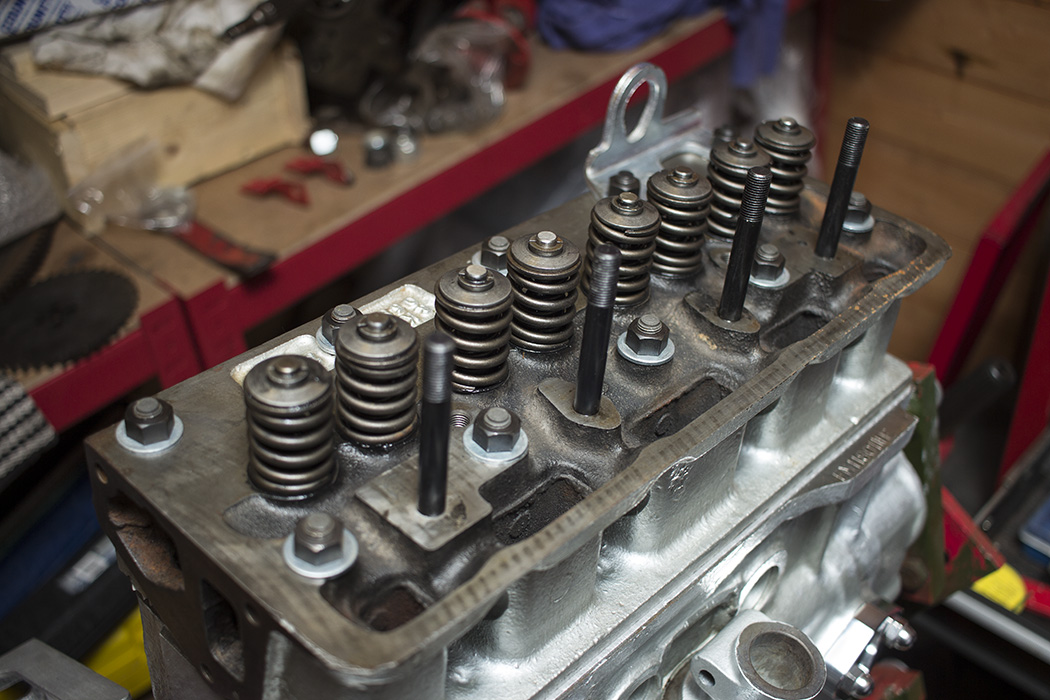
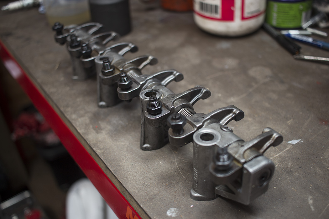
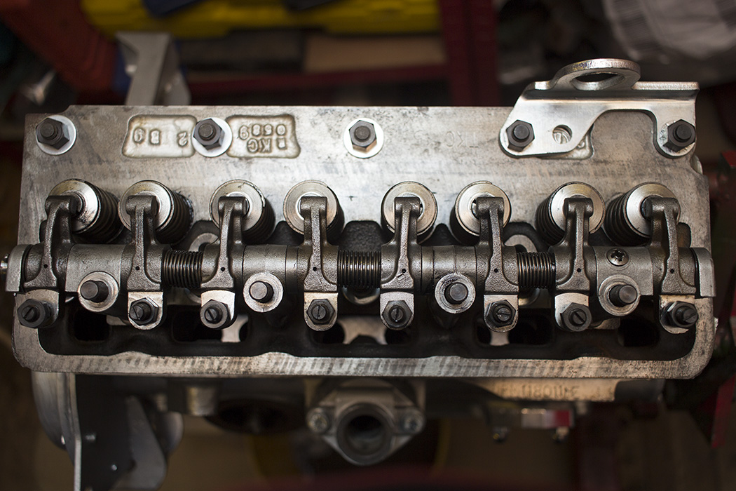
 Now I could bolt my rocker assembly on. I rebuilt it last year with a new shaft and new rocker arms since the old ones were quite worn. This wouldn’t be good for maintaining oil flow since the shaft is just fed from one end.
I checked the contact area of each rocker pad on the valve stems but found a problem. The contact area was terrible on some of the rockers. The bad ones seemed to be a different manufacturer as they were a different shape near the adjuster and didn’t have the letters “PT” stamped on them. I went back to the supplier and started asking around other suppliers to see if they’d heard about any problems with the quality of rockers. I bought another pair from James Paddock but the right hand one was the same.

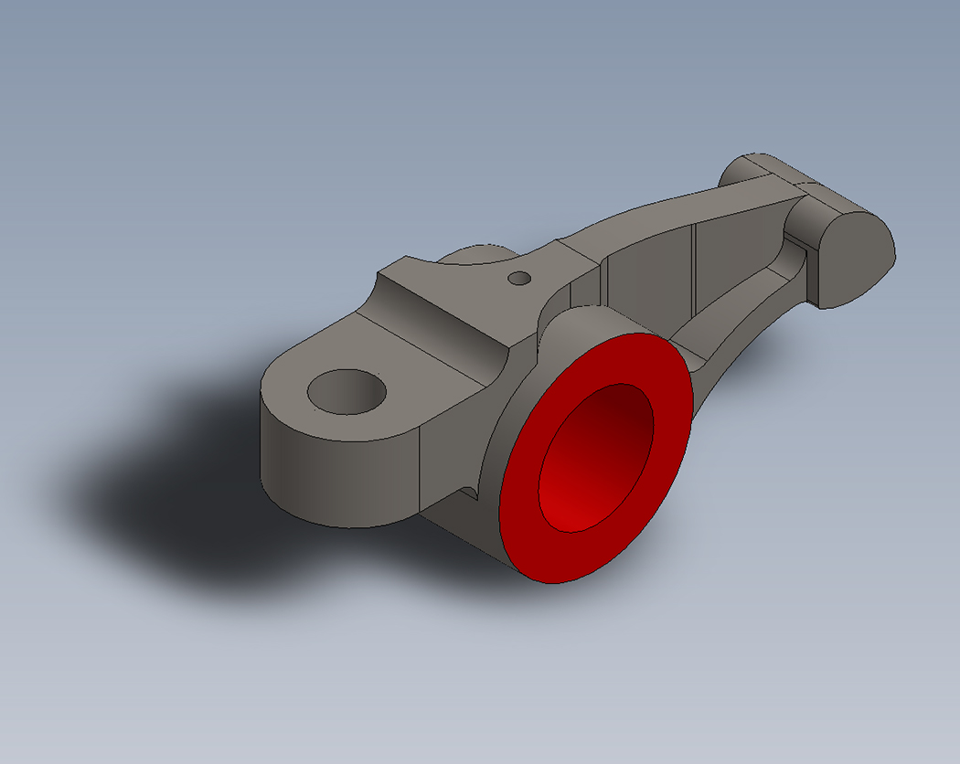
Rimmer Bros acknowledged the problem and sent a replacement set out. Still the same. I was beginning to think that well made rockers just don’t exist. I called upon some work colleagues again. This time with the idea of making some rocker arms from scratch with a slightly increased ratio for more lift. I test fit a 3D printed part and made some changes to the dimensions. Next stage is to get an arm machined but we are in the middle of a big project at work so the rocker situation would have to wait for now. If it works out and I have a set made they will be made from 2312 tool steel which I will send off for nitriding so they are reasonably hard and have some wear resistance.
While all this was going on with the rocker arms I made up a baffle for the sump to fit with the older style straight pickup. My thinking was to direct all the returning oil to the pickup and also keep enough there while braking and cornering. After messing around with a cardboard template, I came up with a design that would incorporate a hinge in the bottom. This would allow oil to enter the boxed off section of the oil pickup while cornering but not let it out. I also added some mesh with the idea that it might keep the oil from getting whipped up and full of air.
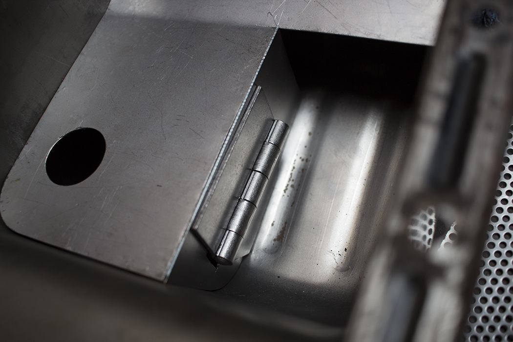
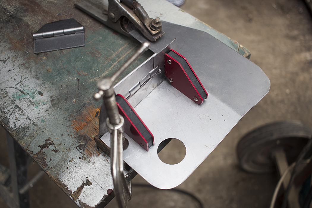 My welding isn’t great but it does the job!

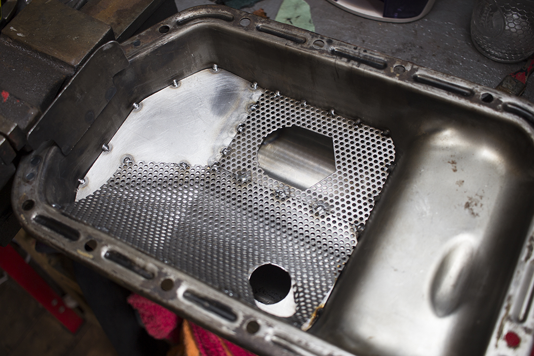 I carefully tacked it all in without too much continuous welding so it didn’t get too warped. In the end it was a good fit and I think it should do a reasonable job. Now that was done I could clean up the outside of the sump, paint it and bolt it on.
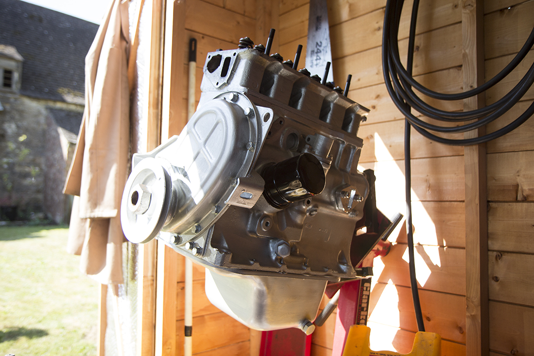
Since the weather has been warming up recently, I’ve been concentrating on parts that need painting. Just some suspension bits etc. The engine is going to need a few more things doing to it but it’s 90% complete. I can do the rest after it’s bolted to the chassis if I need to. Hopefully I’ll be able to start putting paint on the bodywork later this year.
One thought on “Spitfire Engine”
Thanks