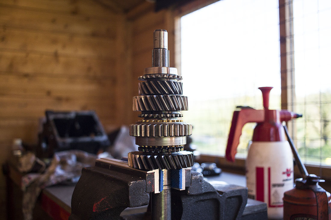
When I first took the Spitfire off the road I thought it would be best to exchange the gearbox for a reconditioned one as some of the parts were a bit scarce. I saw a single rail (non-overdrive) gearbox on eBay not too far away and decided to take the chance on it so I handed over a tenner and took it home as a donor box for my own which has overdrive but shares most of the parts.
I opened it up to see what condition it was in, pretty much everything was excellent. All of it better than my current one anyway. I’d hit the gearbox jackpot. First job was to strip both gearboxes down and start selecting the best parts. Given that I’ve rebuilt (with limited success) the gearbox a couple of times in the past, I have quite a collection of various parts which includes a mountain of synchromesh rings.
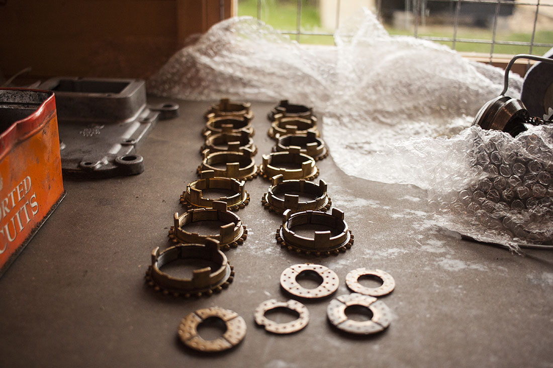
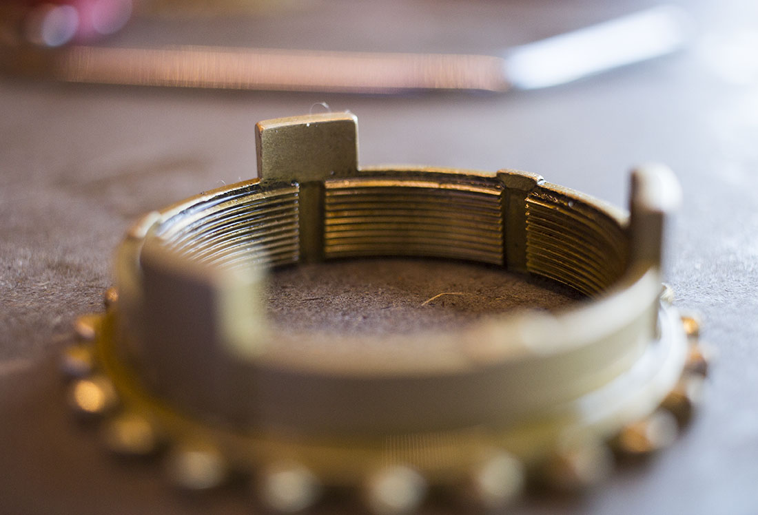
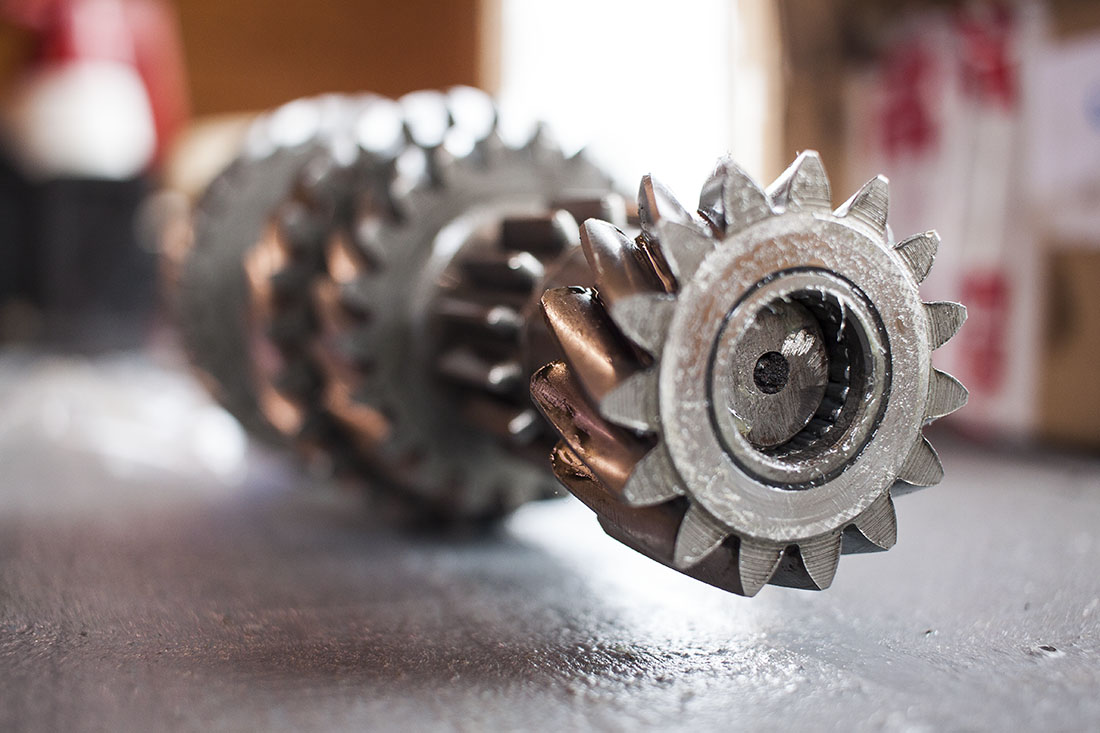
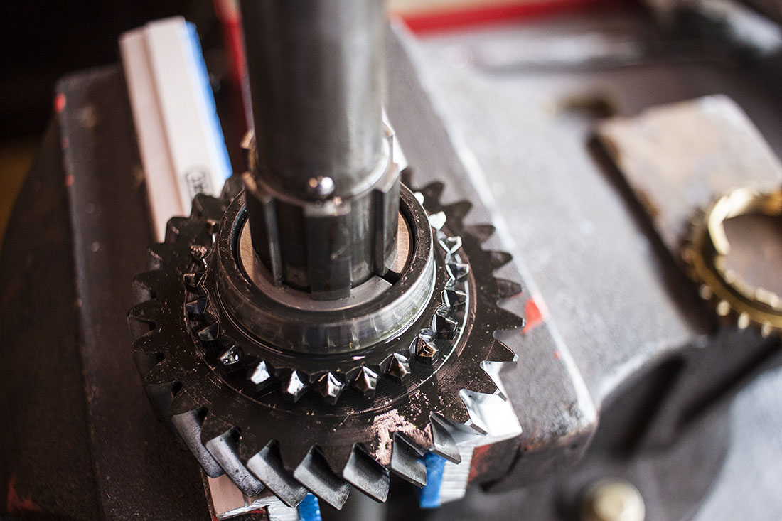
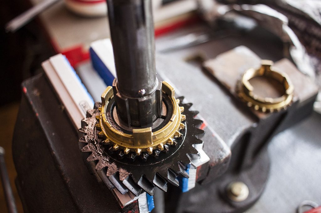
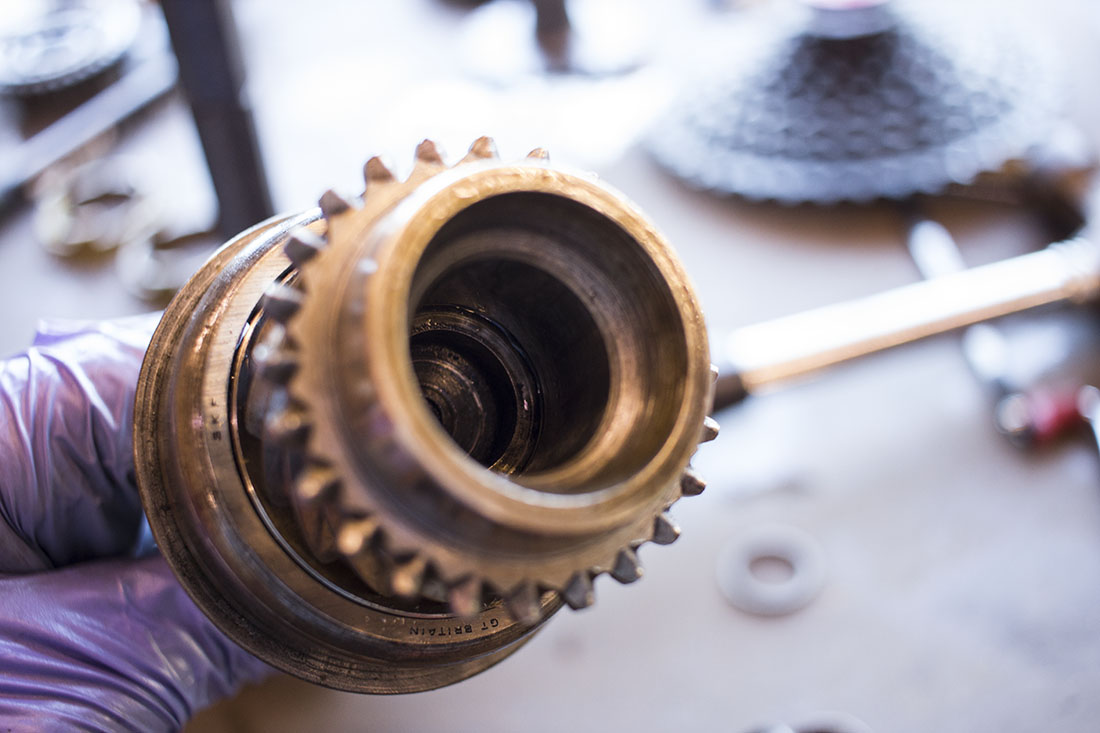
Many of these I have bought new in the past but there has been an issue with the quality of some of them which has made them practically unusable. The first image below is a newer replacement. You can see that the little raised bits that sit on the synchro hub are completely missing and the teeth are not very well formed. In fact the whole casting looks pretty rough. The second image is one out of the donor gearbox. It has the little raised bits that make it stand off the synchro hub (and therefore make better contact with the cone part of the gear). The teeth are formed much better. Comparing the two on a gear, it’s immediately obvious which is going to work better so I selected four of the best out of my vast collection.

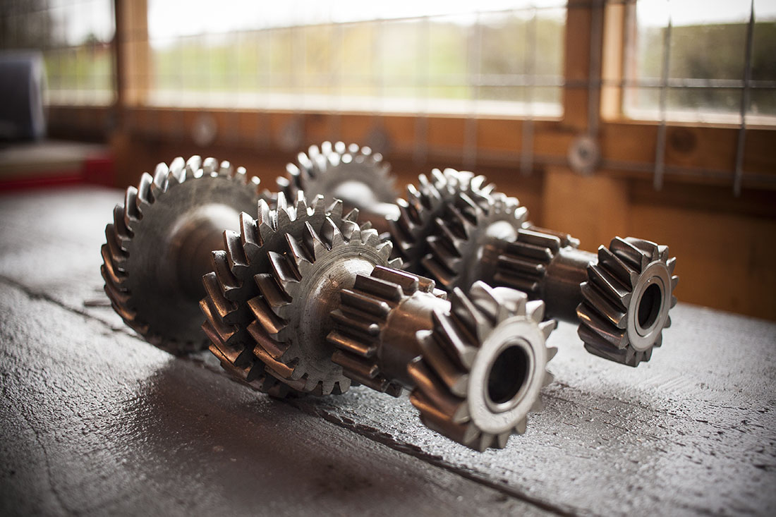
Next was to choose which layshaft to use. There wasn’t much in it between these except for fewer chunks taken out of the reverse gear on the donor. I thought it would be best to use that since I was going to use all the gears from the donor as well and they will have been meshed and worn together for some time.

Before I started I had a rebuild kit to hand which includes gaskets, layshaft needle rollers, layshaft (inner shaft), bearings and seals. First step is to fit the new needle rollers inside the layshaft (25 each end) with grease to keep them in position. With the old layshaft, I had cut the end off so it’s just shorter than the layshaft cluster itself. This means you can then lower the layshaft cluster in to the gearbox casing while keeping the needle rollers in place.
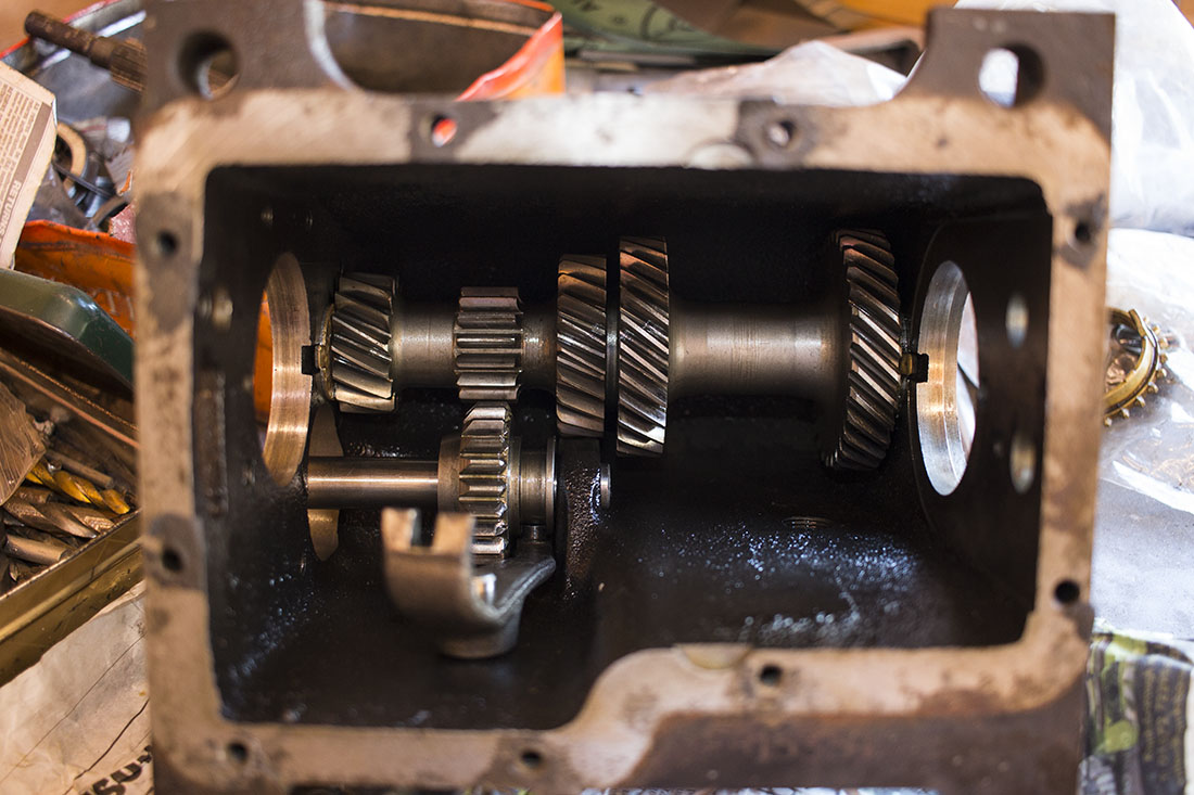
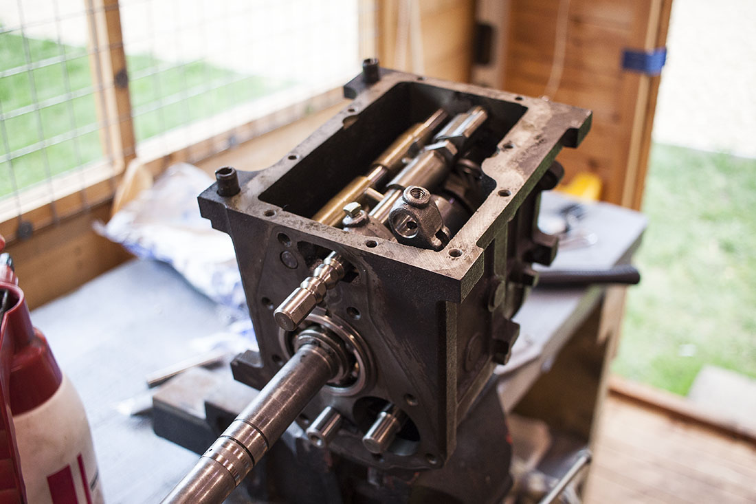
After selecting two good condition thrust washers, reverse idler gear and shaft—the layshaft cluster can be lowered in (to a nice clean gearbox casing!).
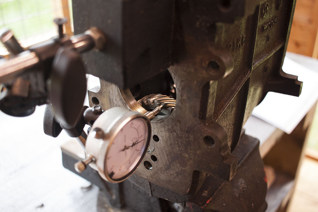
Once the layshaft is in, the end-float can be checked to confirm the thrust washers are within spec. The spec is 0.007-0.015″ (0.178-0.381mm). After I checked mine it was slightly lower than the spec (around 0.15mm) but I think it’s better to be on that side than too much. Given that there is only a limited selection of thrust washers available, that’ll have to do.
That’s about it for the layshaft until everything else is in. Next up is the mainshaft. First gear, split collars and thrust washer can go on. Then I sat the shaft in some soft jaws on the thrust washer.
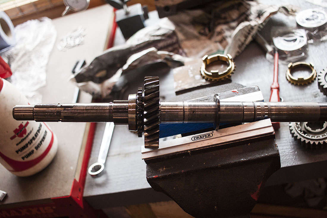
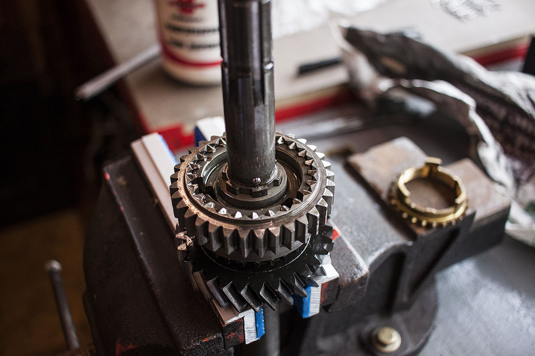
From there the synchro ring for first gear can go on, followed by the synchro hub for 1st/2nd gear. This goes on a specific way, you’ll notice the splined central part of the hub is slightly longer on one side, that faces 2nd gear (up in this case) and the reverse gear teeth on the outer part of the hub also closest to 2nd gear. I was doing all this while trying to keep things clean and lubricated so synchro rings don’t get damaged etc.
 When it came to fitting 2nd gear I seemed to have a bit of a moment and put 3rd gear in by accident. It fits the shaft in the same way and isn’t all that different in size with the exception that it doesn’t quite contact the synchro ring. I thought I had the wrong thrust washer for a while and even had a chap at work grind a spare one down in 0.2mm increments to make it fit. Finally it dawned on me and I installed the correct thrust washer and 2nd gear instead of 3rd! Synchromesh engaged as it should after that! The thrust washer for 2nd has a small cut out for the BB that’s in the shaft which I can only assume is to stop it rotating and wearing the shaft itself.
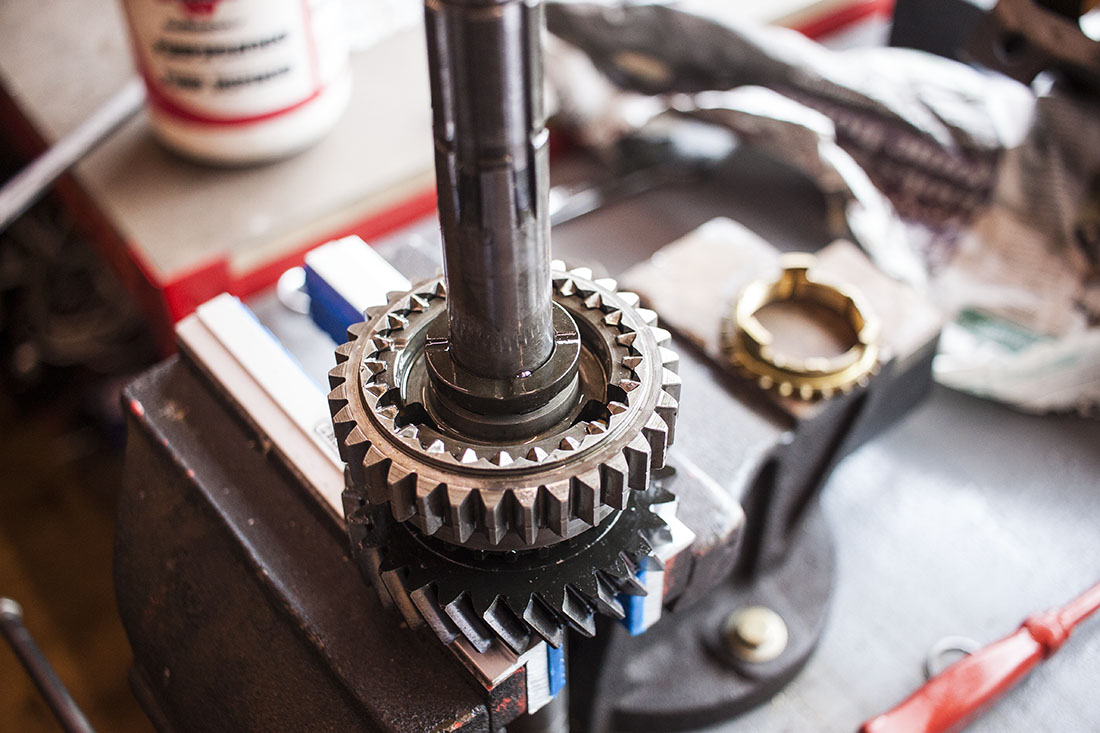
In order from the bottom up. Thrust washer, first gear, split collars, synchro ring, 1st/2nd synchro hub, thrust washer (BB slot), synchro ring, 2nd gear, gear bush (inclusive of thrust washer), 3rd gear, gear bush, splined washer and finally the snap ring that holds it all together. It’s worth bearing in mind to keep 1st gear up against those split collars so they don’t fall out from this point.
In addition to the components on the shaft above, the 3rd gear synchro ring and synchro hub need fitting as they can’t be installed after the shaft and bearing and in the gearbox casing. The manual specifies the use of a special tool to hold the mainshaft centrally in place while the bearing is fitted. I didn’t have one specifically but found that part of my bearing puller was almost made for the job.

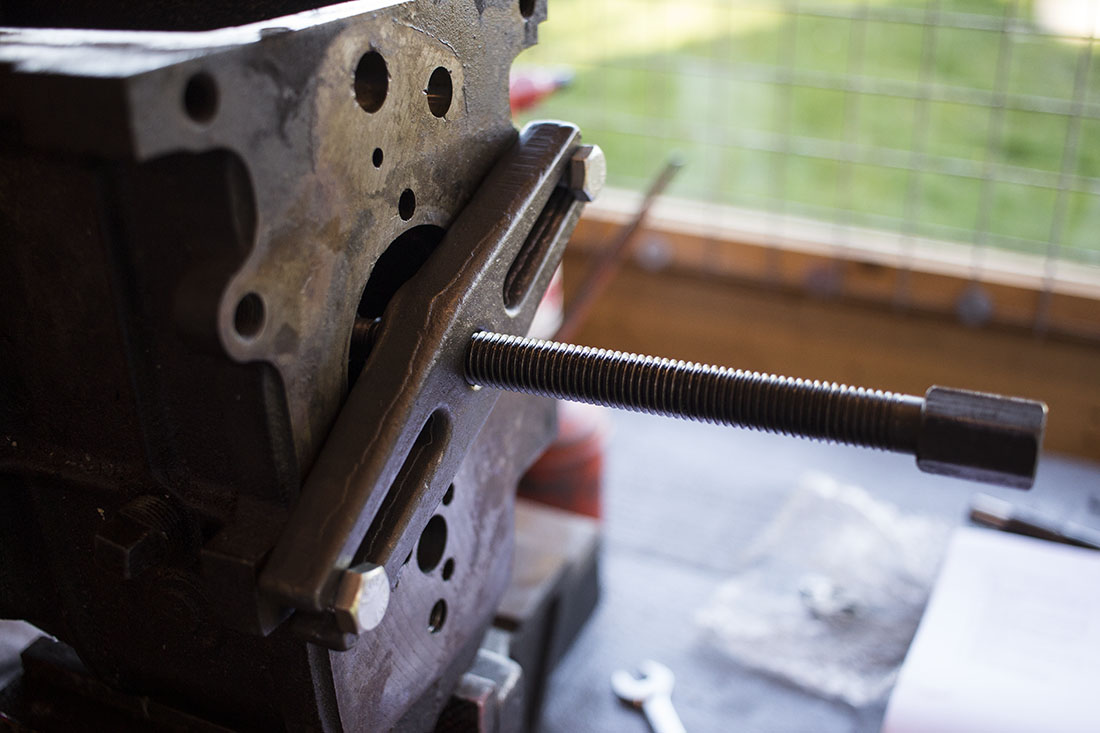
With the shaft centralized the bearing can be fitted. Ideally something that’s roughly the same diameter as the inner race but long enough to clear the end of the shaft would be ideal but I used a drift on the inner race which I think is okay if it’s done evenly.
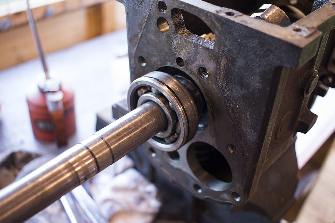
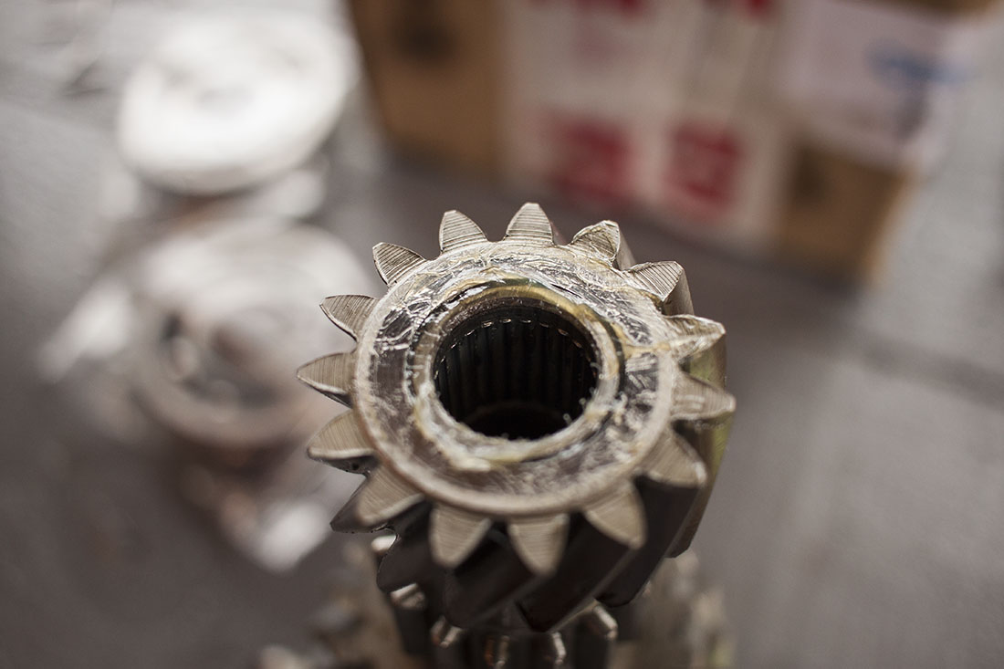
Once the bearing is in the outer snap ring, washer and circlip can be fitted. In most cases I measured the thrust washers and spacers that I had available and used the thickest ones to account for any wear. The final synchro ring, needle roller bearing, two spacers and input shaft can be fitted now. The end of the mainshaft fits inside the input shaft with the spacers and the needle roller bearing. The input shaft on my donor box is slightly different from mine but the bearing was good anyway so I basically used mine as it is which is a shame because the dog teeth on the donor input shaft looked better. Hopefully the synchromesh ring that I’ve chosen will be good enough and selecting first gear won’t be a problem.
 Once the input shaft is in, all that’s left to do is to raise the layshaft and fit the gear selectors and shafts. Rimmer Bros. had an offer on selector shafts which I got for a couple of quid each. Anything to help a nice, positive feeling gear change. Raising the layshaft in to position isn’t too difficult. One end will tend to get wedged in the correct position which gave me a chance to slide the new layshaft in behind the dummy shaft and jostle the rest of the layshaft cluster in to position.
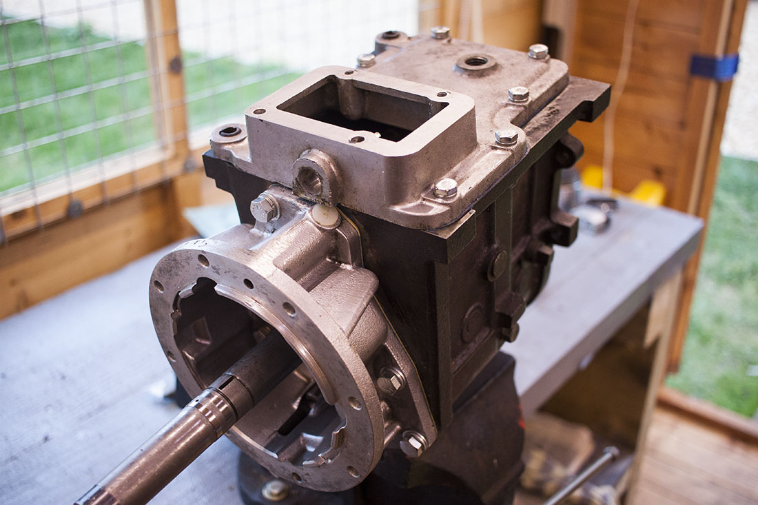
The top cover can be bolted on with a new gasket and a smear of instant gasket just to make sure. The surface of the gearbox casing isn’t really that flat so I think a bit of instant gasket should just make sure there are no leaks.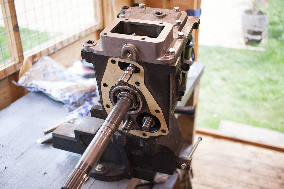

The spacer for the reverse idle gear can go on now before the overdrive adapter is bolted on. That’s about it as far as the gearbox itself goes. I feel more confident that it will work better this time having replaced some troublesome gears with bad dog teeth and selected some pretty good synchro rings. Next up is the overdrive…
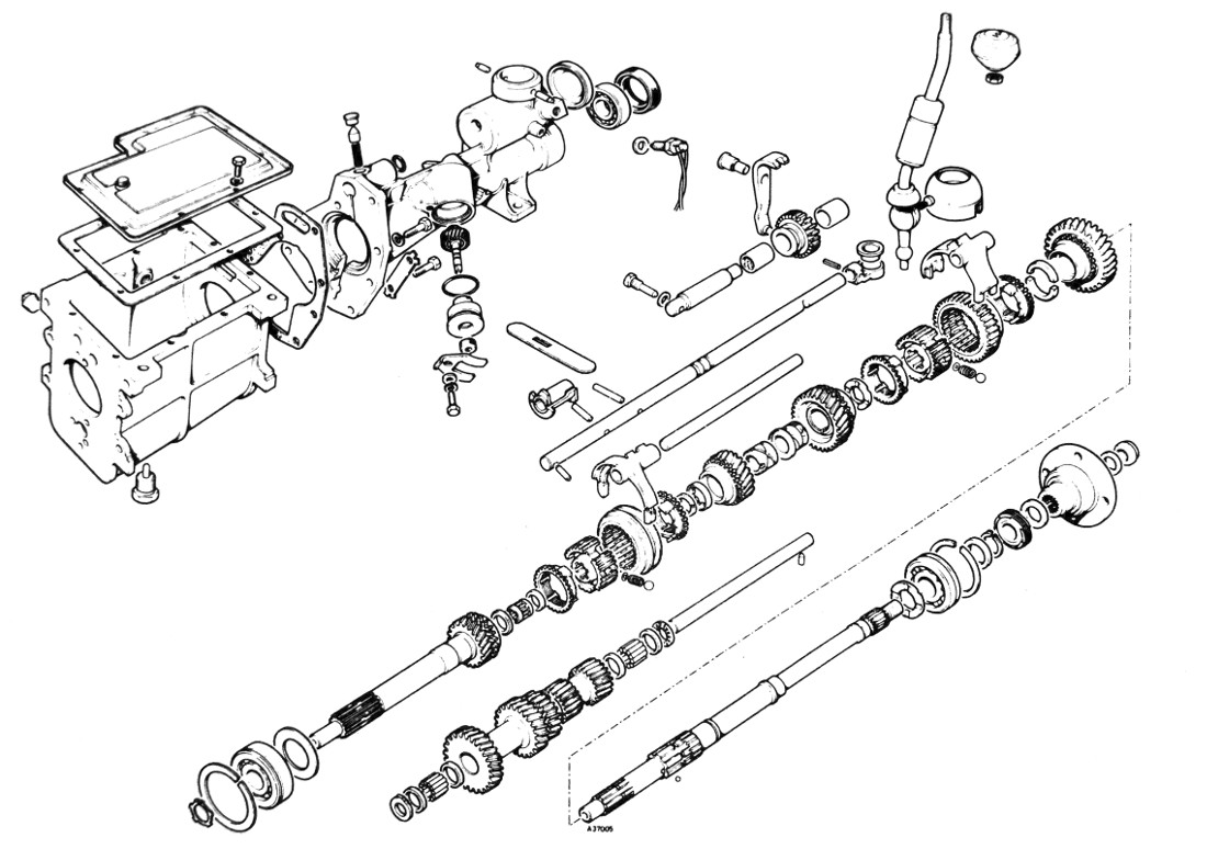
By the way, this image came in useful for the rebuild…
9 thoughts on “Spitfire 1500 – Gearbox Rebuild”
Thanks for the run down, was a help in a few key places, managed to get our box back together. If you ever do this again a photo just prior to the input shift going in would be great. But great colour photos that you have are great. Thanks.
Joe, a great description! I will have to re-build my Spitfire’s box soon and this certainly will help.
I see you have a red spit 1500 repair manual,i have a white one,i’m wondering if your manual shows how to remove the gear lever rail and alloy top cover and connector block to access the gearbox,i don’t want to ruin a good box by force,albeit i’m going to overhaul it,bearings and whatever else looks suspect,then the O/D gets a refit.
My manual doesn’t go in to how to do that on the overdrive spec top cover specifically (which is different from the standard box without overdrive) but from memory, you need to unbolt the bracket that supports the gear lever from the top of the overdrive. Then remove the small pressed steel cover on the top of the gearbox. Under there you will find a square head bolt that goes through the selector shaft, remove that and the shaft should slide out. It will need some force to overcome the spring loaded detent. Then the main cover of the gearbox should come off after removing bolts. You might need to pry it a bit near the roll pins that align it.
Edit: In fact, looking at the images, it’s the selector shaft iteself that has the detents on it so you shouldn’t need to worry about those. The shaft from the gear lever should pull straight out.
Hi Joe, I have a question about gear mesh. When in 1st gear, is it normal for the 1st/2nd syncro hub to be engaged with the reverse idler gear? On my Spitfire single rail box, have a whining/gear mesh noise when in first. One internet source says the syncro hub and reverse idler are in mesh when in reverse. Of course the idler is able to freely spin since it is not engaged with the layshaft. Your thoughts?
I’m not 100% certain but looking back over my photos suggest that the reverse idler gear should disengage from both the synchro hub and layshaft. There’s a space for it to sit completely disengaged as far as I can see. Is your reverse idler gear definitely on the right way round?
Hi Joe, thanks for the quick reply. Yes, the reverse idler is installed correctly. Gearbox does work and shift correctly in all gears. No sync issues, no other grinding sounds. Just the gear mesh noise in first, regardless of speed or clutch engagement. The more I study this, I’m becoming convinced that while not intended, this is a common issue. There are plenty of pictures on the internet of the 1st/2nd sync hub gear with damaged teeth tips just on the 1st gear side. The reverse idler has complementary damage on its gear tips. The only way this damage can happen is with 1st gear engaged; when the sync hub gear is in close relationship with the idler gear in its disengaged position. Some may think this damage is from poor shift practice into reverse. But the damage is from both gears rubbing against each other at speed as the damage is polished. Reverse shift happens with the clutch engaged and the vehicle stopped (or nearly) so no relative motion between these gears.
Anyway, that’s my thought at the moment. Unfortunately, I have no idea how to adjust gear float or any other adjustment to stop this! Thanks for your time.
That’s an interesting theory
This may not apply, but some folks take the single rail internals (larger needle bearing between 1st-motion/3rd motion shafts) and install them in a 3-rail 4-synchro OD box that they have. But they run into this reverse idler problem, less space in the 3-rail case? but the length of the spacer(s) on the idler shaft, and the shape of the actuating arm for reverse.