Now the body had been repaired, epoxy primed and sealed, I moved on to the chassis. I have actually been here once before and started to build up a rolling chassis a couple of years ago. I wasn’t pleased with the paint job though so the chassis went off to be stripped with the rest of the car. I basically had to start again. At least this time I would have the opportunity to get it right. I’ve learned a thing or two about painting since last time. Preparation is the key. By the time you’re putting colour on to a surface, all the hard work should have already been done and if you follow the datasheets, you can’t go far wrong.
My thinking was that I would get the chassis rolling before I paint the shell so I could drop the shell straight on. It needed a little welding here and there since it was a bit thin in places. On the whole though, pretty solid and straight. Chemical stripping isn’t cheap but it’s definitely what I would choose over anything else in future because it reveals all and means you know exactly what you’re dealing with from the start.
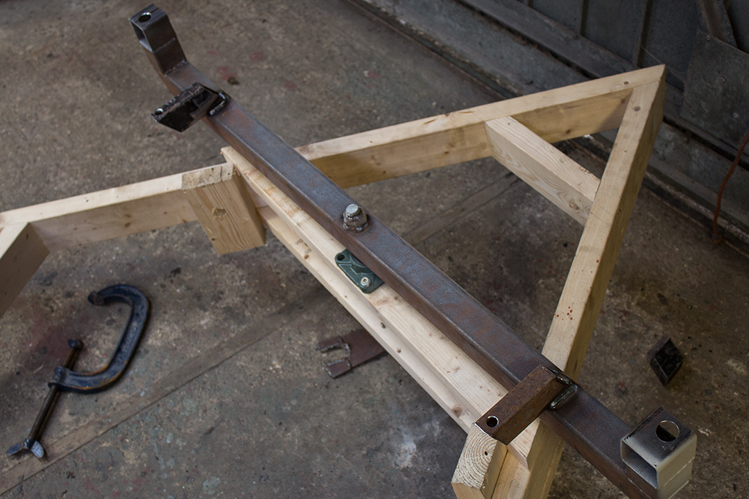
Before I could start work on it I had to modify the rollover jig to accept the chassis. This wasn’t too tricky and the chassis is only about a foot longer than the body shell so it was almost there anyway. The chassis was nowhere near as balanced in the jig though so rotating it is a lot harder.
Once the chassis was in the jig and the welding was done, I set about degreasing and cleaning ready for the internal frame coating. I used Buzzweld cavity paint which should stabilize any rust that remains. I used 6 aerosol cans in total, rotating the chassis as I applied it to make sure I got good coverage.

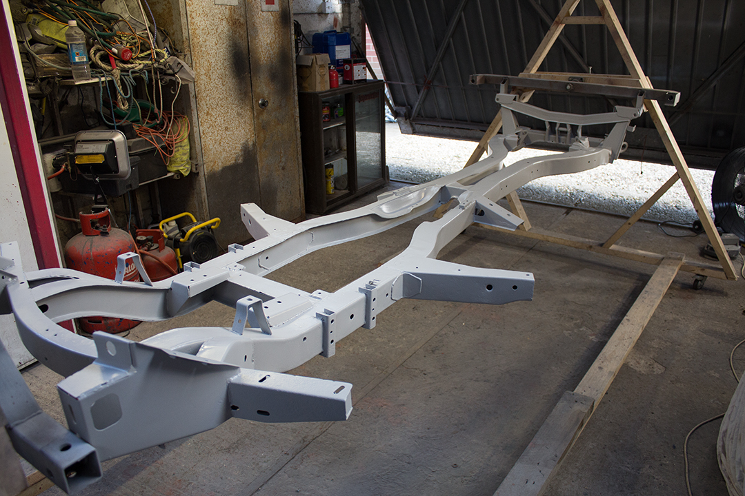
After that, it just had a once over with the mini DA sander to clean up the cavity paint that had leaked out of the holes. Then it was simply a case of applying the epoxy primer followed by 2K acrylic.
For the epoxy primer, I reduced it with 40% thinners. Straight after a couple of coats of that, I could mix up the 2K acrylic and apply it directly over the epoxy without having to let it dry and key it. Epoxy seems to stay softer/tackier for longer than high build which I think is why it lends itself to the wet-on-wet method because it has quite a long re-coat window. Wet-on-wet is ideal for something like a chassis that doesn’t really need a perfect finish but just good adhesion and coverage.
Since the chassis is so intricate, I used a small 0.8mm detailing gun and narrowed the pattern right down to a spot. This meant I could get the hard to reach areas from a distance by shooting the paint into tight corners. I finished up with a 1.4mm nozzle to get a nice flowing final coat. The result was much better than my first attempt which sort of failed and I ended up with peeling paint. I used POR15 the first time I painted it. I don’t think it has any benefits over epoxy and it’s way more expensive. I left the primer stage too long last time. It hardened and then the top coat had nothing to adhere to.
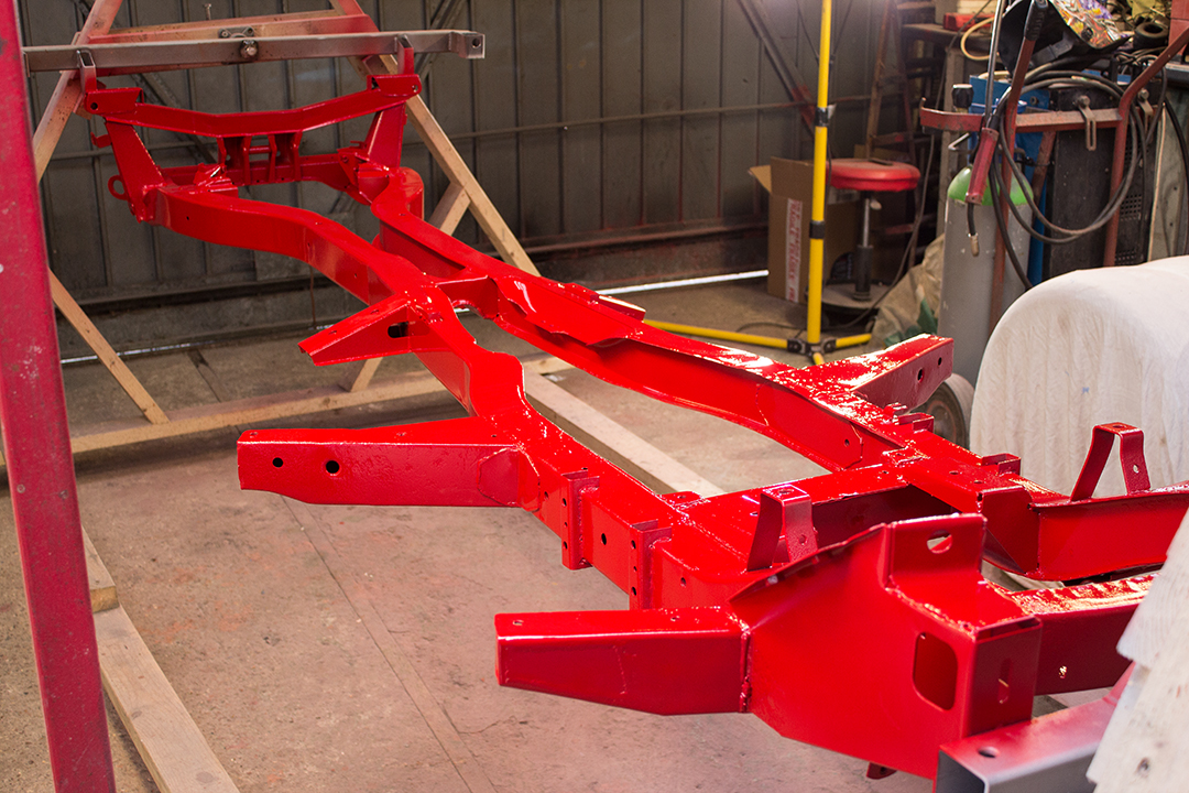
The final part of getting the chassis ready to build up was applying “Zero Prep” by Buzzweld inside the chassis which is a clear cavity wax and should just give another layer of corrosion resistance. I masked off the smaller holes of each section of the chassis and applied the zero prep with the PCL gun they supply. Zero prep comes ready to use and is like a light oil. It becomes dry to the touch and remains transparent.
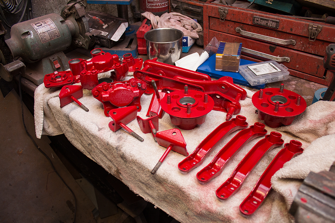
Now the chassis was ready, I started getting the suspension bits together. I’d already built up the rear axles and some of the front suspension parts but since I’d got a much better finish on the chassis, I decided I should strip them and do them again. I borrowed a sand-blasting cabinet of a friend this time. Wow, what a difference that makes. With medium grade glass, it leaves the perfect finish for painting and you can really get in all the nooks and crannies to remove rust and paint. Several days of sand-blasting and everything was ready for paint.
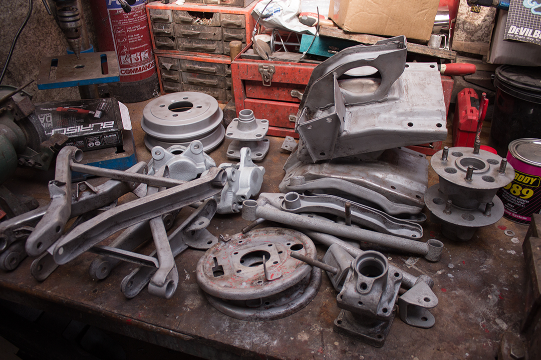
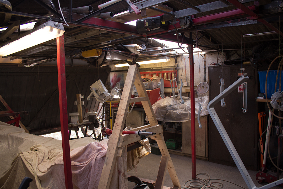
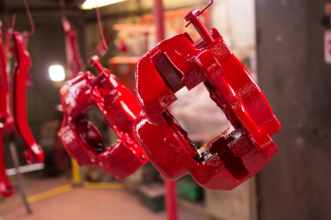
I degreased everything and hung it up ready to paint around the garage which ended up looking like some kind of weird art installation. On to the epoxy and top coat, using the same process as the chassis.
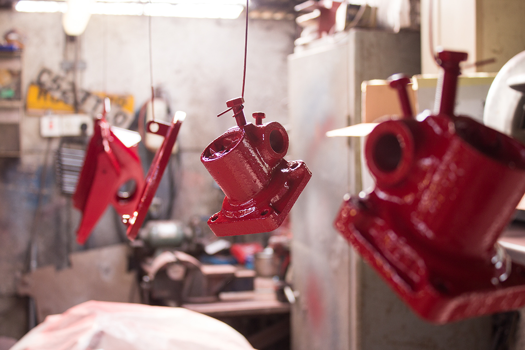
I used my small, 0.8mm detailing gun for all the suspension parts. It’s ideal for this kind of work. Somehow spraying bright red paint is very satisfying and I was pleased with the results for sure.
I removed the chassis from the rollover jig and supported it on some trestle stands ready to start assembling the suspension parts. I removed all the masking tape from bearing surfaces etc. and started to build the front and rear hubs.
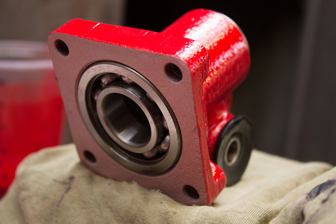
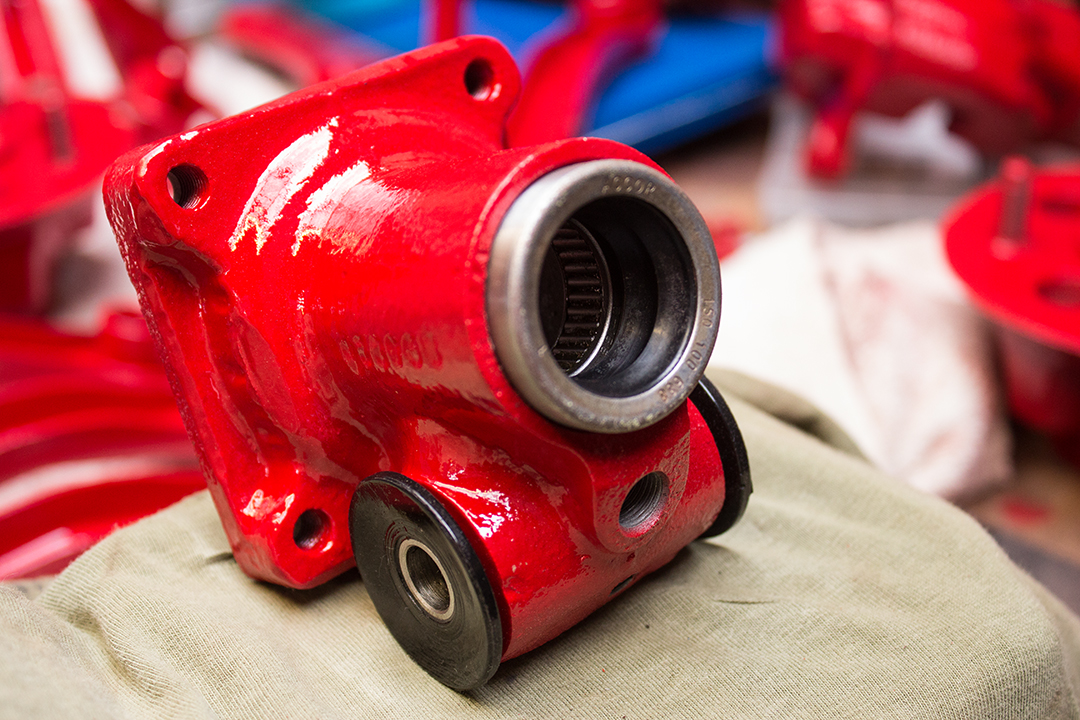
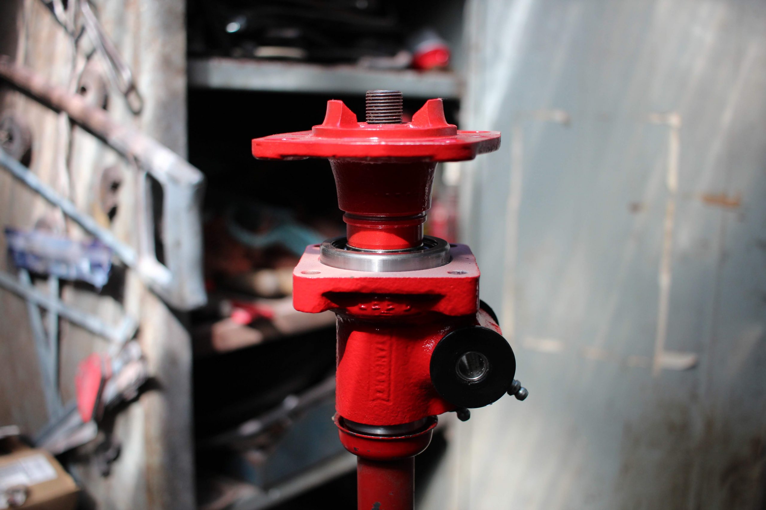
I fitted new bearings in the rear hubs. This is the first time I’ve ordered a rear bearing kit and found modern rubber in the oil seal. Traditionally the oil seal in the rear hub is a leather type that requires soaking in oil for some time before fitting. I was happy to see a more modern alternative. I also replaced that terrible nylon rear trunnion with a SuperFlex poly version. Much easier to fit and far less likely to turn in to a corroded mess as well.
The front hubs already had new bearings fitted from the first time I built them so it was just a case of refitting these. The front hubs have a felt oil seal in the back which is always really tricky to fit without bending it out of shape. I managed to get them in, albeit a bit mangled. They are concealed by a cover on the hub so I don’t think they really serve much purpose anyway. I may well upgrade the front once it’s on the road. Canley Classics sell a kit that includes a stronger stub axle, fully sealed bearings, and an alloy hub. Lighter and stronger is always good.
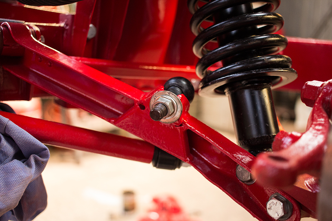
I re-fitted the new poly bushes to the upper and wishbones and installed them along with the suspension turrets to the chassis with new high-tensile nuts and bolts. I had freshly zinc plated all the suspension shims.
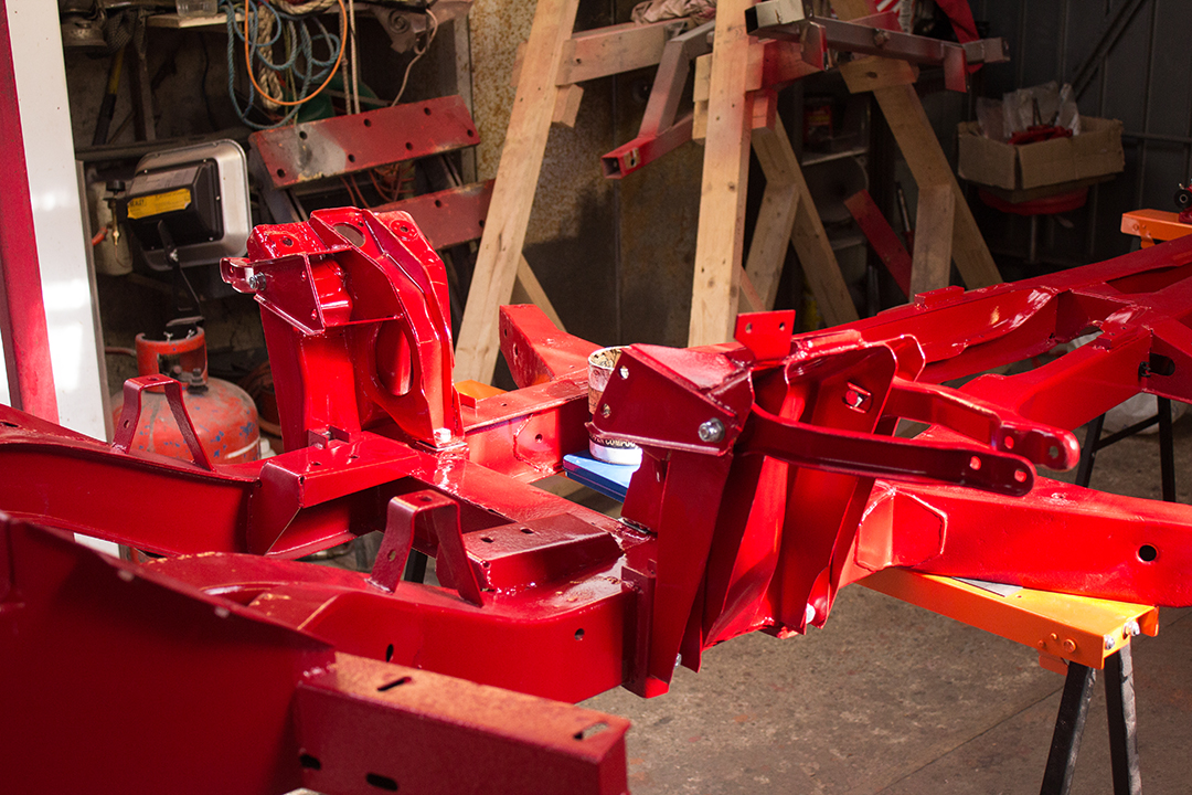
After the lower wishbones were in, I installed the vertical link, hub and disc…
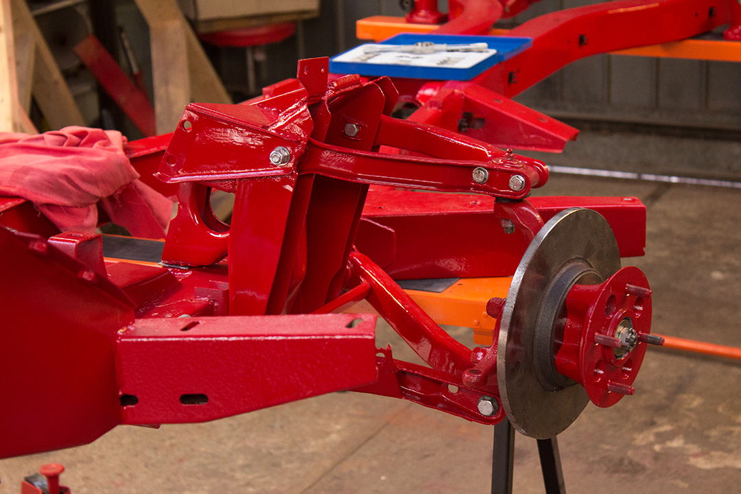
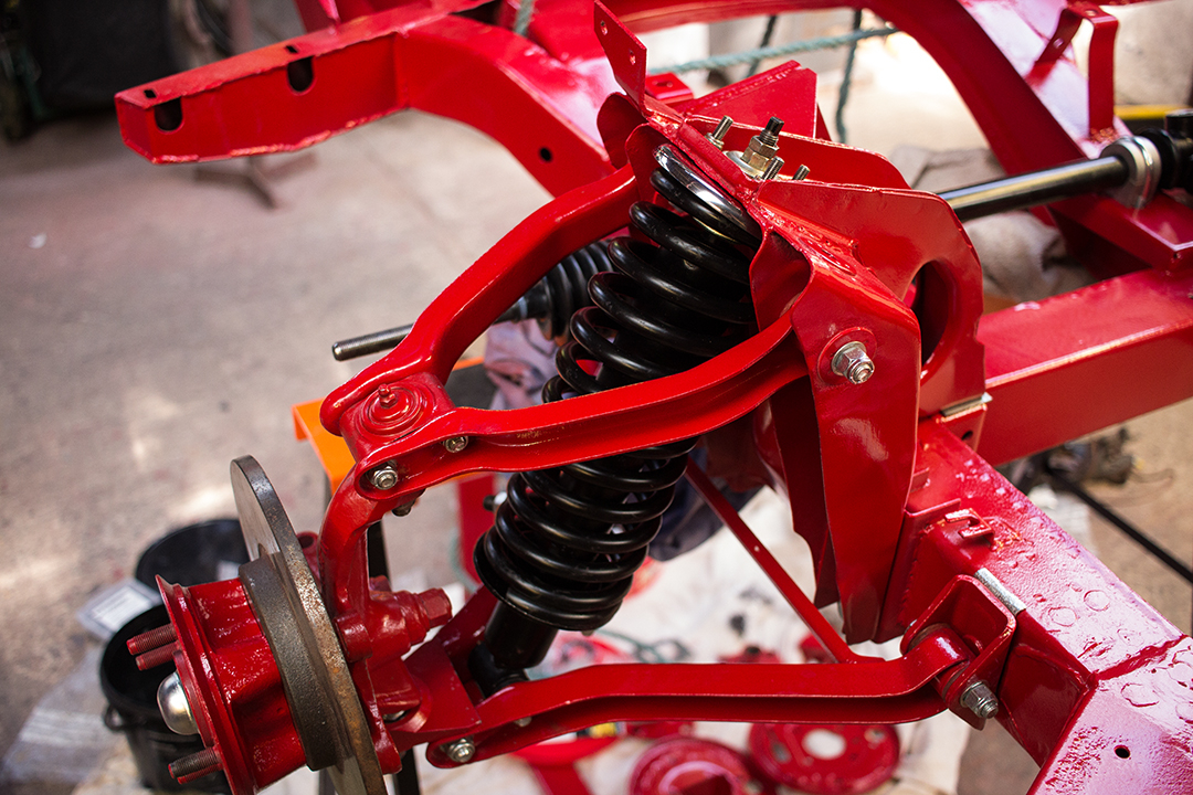
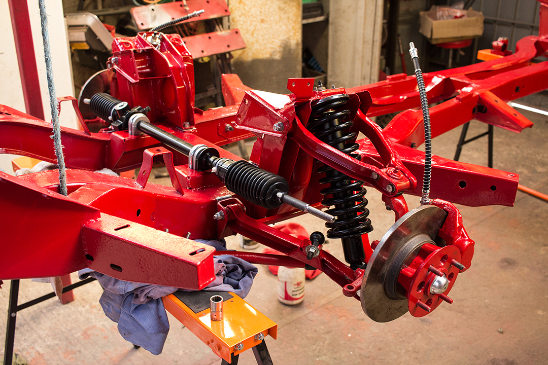
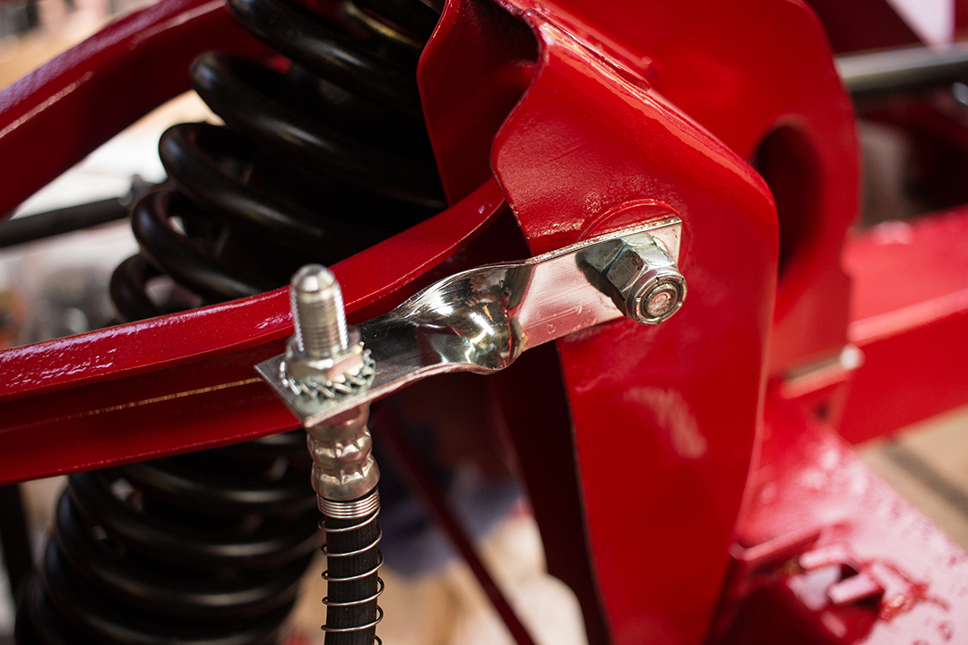
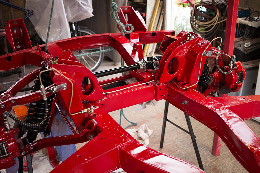
…only to remember that the top link needs to be bolted in after the shock and spring assembly are in, it’s all coming back to me slowly. On with the steering rack and anti-roll bar next. New bushes and anti-roll bar links. I also installed solid alloy steering rack mounts but later decided to go with the original brackets and fit poly bushes for some compliance. I’m not so keen on the alloy mounts after fitting them because they don’t locate the rack laterally and I think they probably clamp down on the steering rack a bit too tightly.

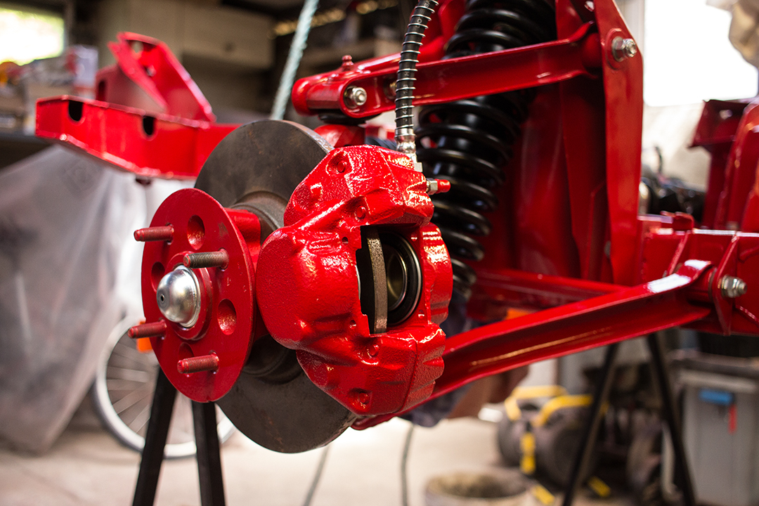
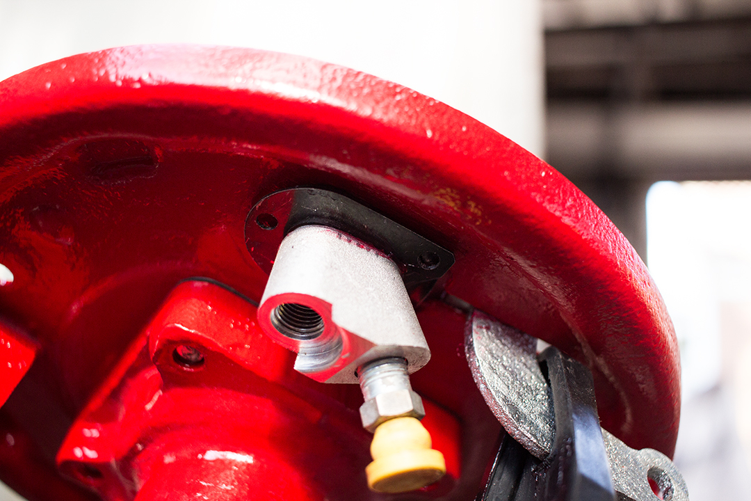
Next, I bolted the calipers on with some shim washers to centralize them over the disc since they would have had disc shields originally which fitted between the caliper and the vertical link. I didn’t have the disc shields fitted before so I didn’t bother putting them back. When I did have them fitted, it only made things harder to keep clean.
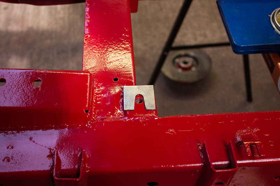
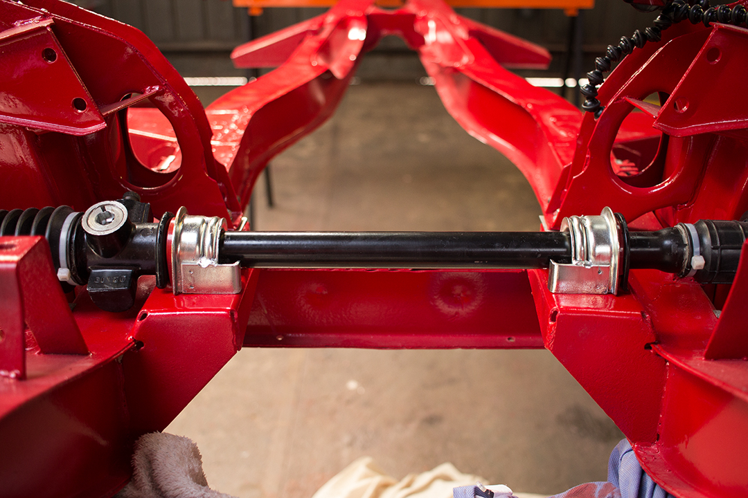
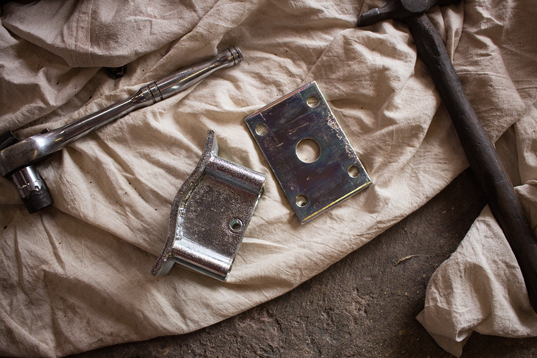
Now I swapped those alloy steering rack mounts for the factory ones which are quite well designed as it happens. The mounting holes in the chassis for the rack clamps are slotted. On the underside, there are two plates with 45° slots in them. They have a bend which butts up against the chassis. As you tighten the nuts, the plates are forced up against the U-bolts. This preloads the bushes. The rack is both centralised and secured laterally. Easy to understand with a decent drawing like the one from the original manual below. This is another area that some of the part supplier websites have wrong because the plate is drawn upside down and makes it look like the plate fits on the top side of the chassis.

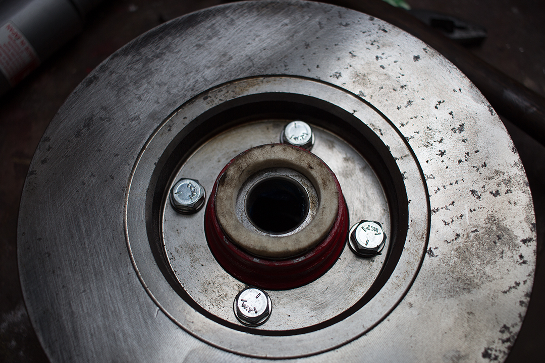
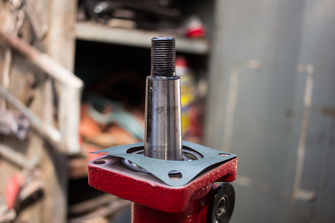
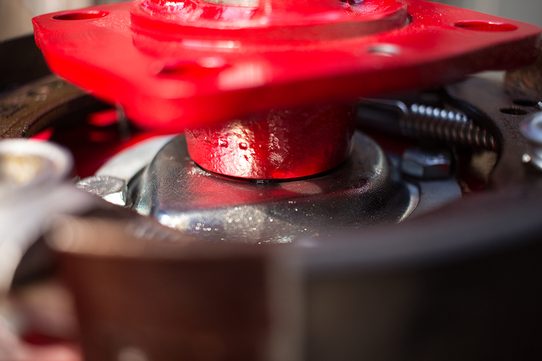
It was really starting to come together now. Next was the rear end. The hub and bearings are located on the driveshaft by the drive flange which is in contact with the inner race of the outer wheel bearing. I find it easiest to put the hub and bearings on and drive it on with the flange in place just far enough to get the washer and a few threads started of the retaining nut. This way the hub will be located correctly on the shaft when the nut is fully tightened.
I removed the flange and proceeded to install the gasket, oil seal, drum brake backing plate and bolts with tab washers. I actually got the oil seal holder in the wrong side of the backing plate the first time round but later on corrected my mistake after consulting the manual. I think there’s a lesson in there somewhere about not relying on the part supplier website drawings. They don’t always tell the full story…
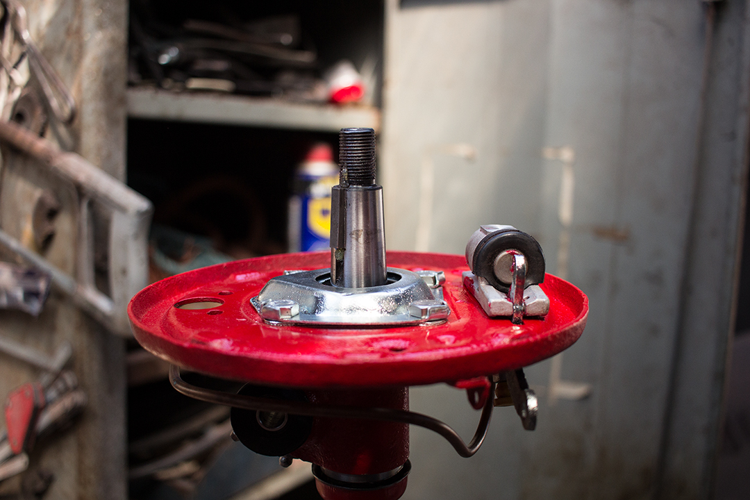
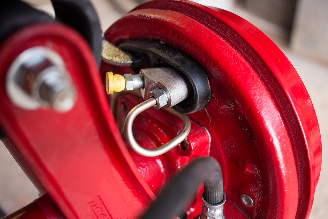
I refitted the new slave cylinders with red rubber grease so they slide nicely as well as the handbrake operating levers which I zinc plated. I also fitted new adjusters, springs, retaining hardware, woodruff key and shoes.
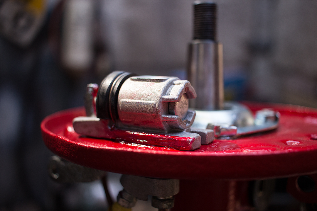
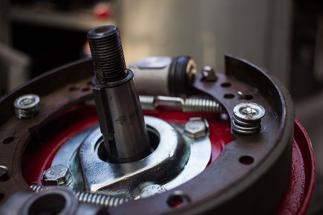
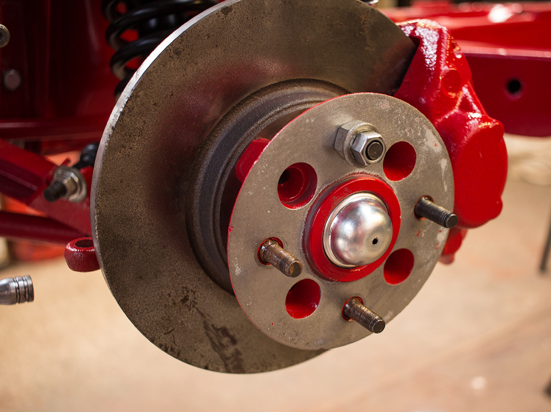
Now the drive flange could be installed. With it torqued down you can see that the hub and brake assembly sits in just the right place and the lip on the drive flange should engage with the oil seal. I installed new wheel studs all around. The old ones were just looking a bit tired. I installed the vertical link ready for the driveshafts to be fitted once the diff was in.
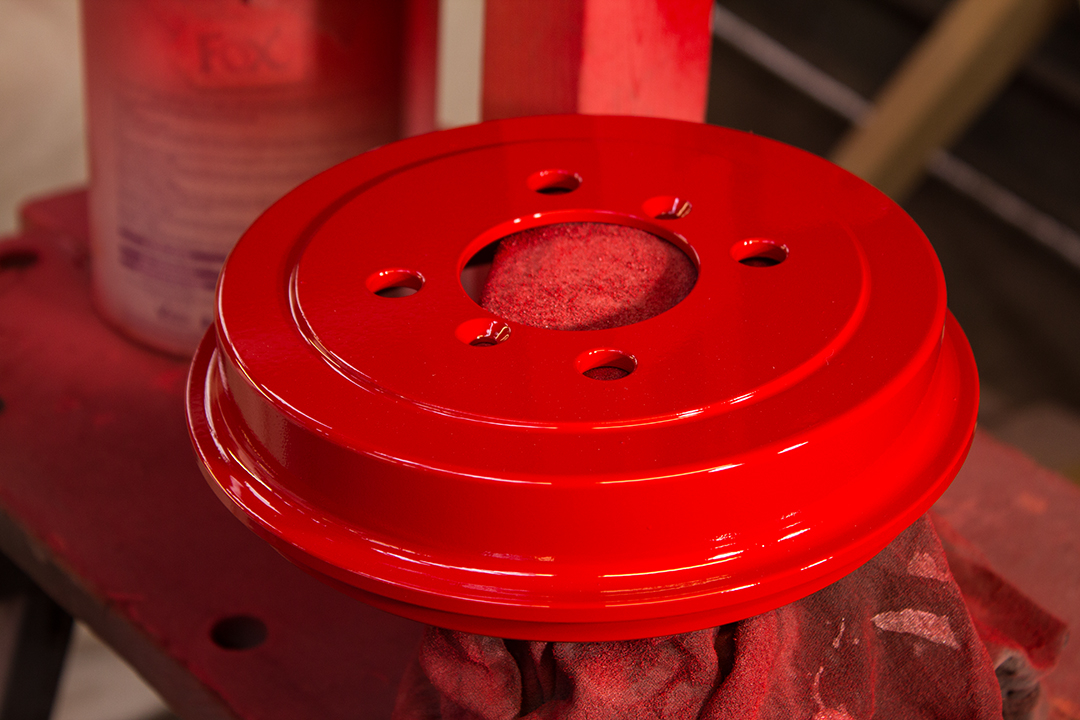
That was pretty much it for the rear driveshafts and brakes. Later on, someone pointed out that I shouldn’t really have paint on those mating faces on the flange, brake drum, and front hubs. Good spot—I removed paint from those areas. Better to have good thermal contact between the brakes and the wheels anyway. I made up some new brake pipe brackets and plated them as well.
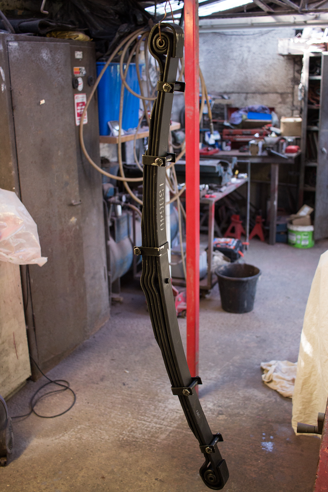
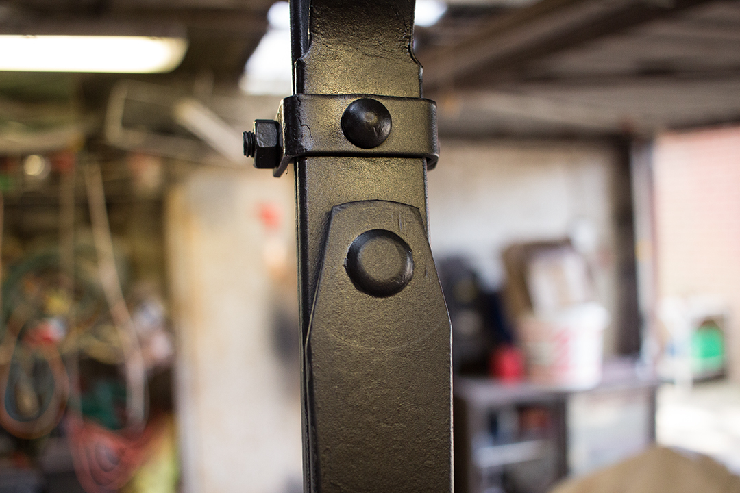
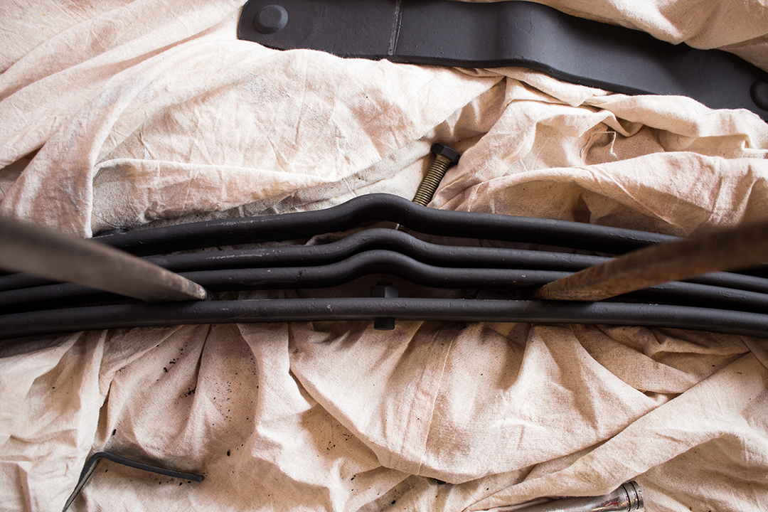
I’ve been using James Paddock recently. I’ve found them to be cheaper than the others most of the time and priority delivery is very fast. I ordered a new leaf spring and a bunch of fasteners, they arrived the following day for just £10 postage.
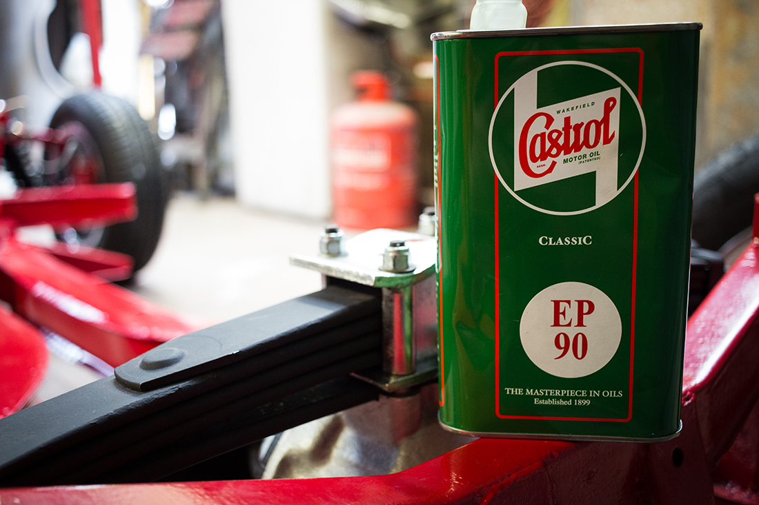
I had originally stripped and rebuilt the old spring but a new one is just over £100. Since the rest of the suspension is brand new, why bother putting a tired old leaf spring back in? The new spring came with bushes so although they are the original rubber type, I kept them. I’ll replace them with poly bushes when they have worn out. I tried Buzzweld’s W.A.R on some parts including the leaf spring. It’s underbody protection spray that’s somewhere between paint and underseal. It leaves a nice matt finish and seems quite durable. It remains flexible so it’s perfect for somewhere like a leaf spring. The new leaf spring was coated but it had peeled off in places so I thought a bit of extra corrosion protection wouldn’t hurt.
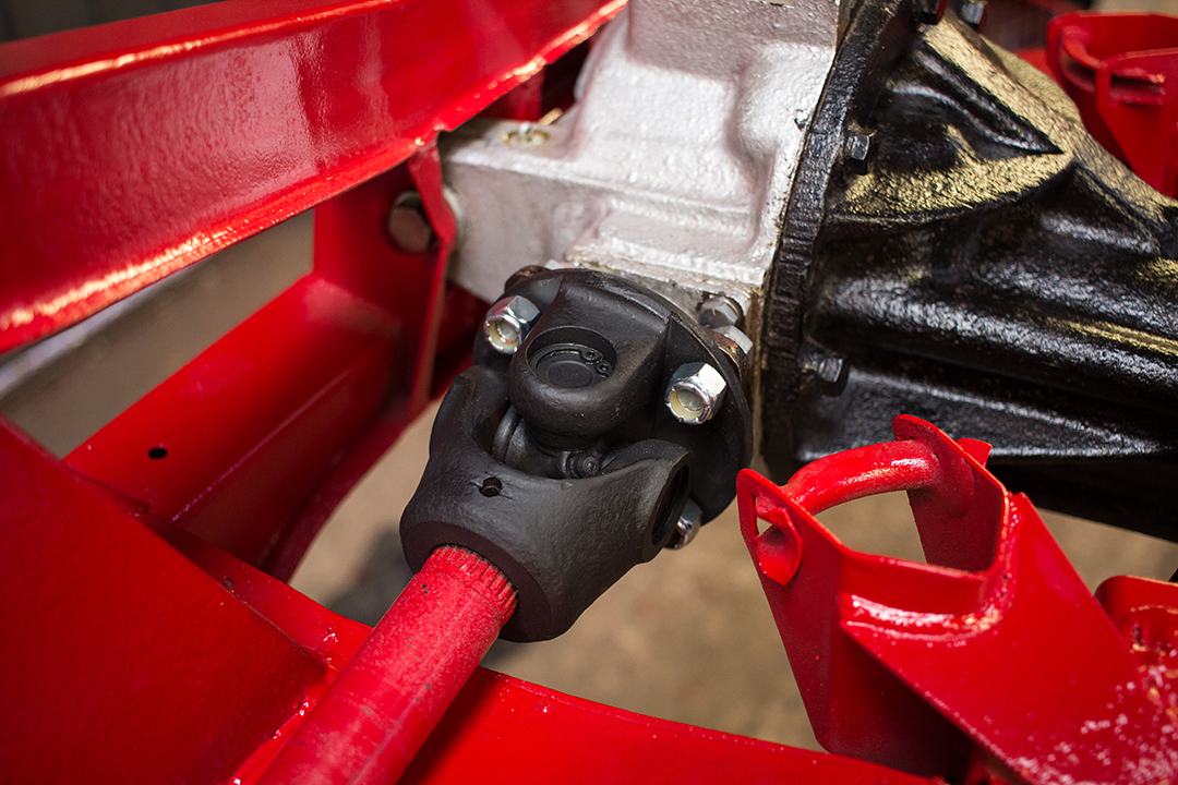
The first part of the rear suspension to fit is the differential since everything hangs from it. I already rebuilt it with new bearings, adjustment washers, cross shaft and seals some time ago. I did a contact pattern check on it and checked the torque for rotating the pinion shaft as per the manual. It’s quite critical to get everything within tolerance. Too much or too little backlash or bearing preload and it’s probably going to whine and clunk when taking up drive. I made adjustments and went through a few iterations of pinion depth/carrier position before the contact pattern looked right and the bearing pre-load was correct. I’ll only know if that was successful when it’s on the road so I’m keeping my fingers crossed for that one. I drilled and tapped the casing for a drain plug too. I’m sure it will last longer with more regular oil changes.
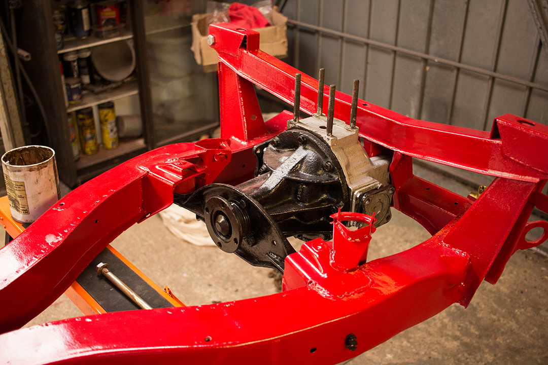
It’s a bit of a weighty beast being cast iron, so getting it into position is a little tricky. I fitted it with new poly bushes for the front mounts with stainless washers. I gave the driveshaft UJs a couple of coats of W.A.R too. I know that if those universal joints are exposed to the elements, they will corrode and get seized into the drive flange and that makes replacement much more difficult. I cleaned up the driveshaft flange mating faces and fitted the driveshaft and hub assembly.
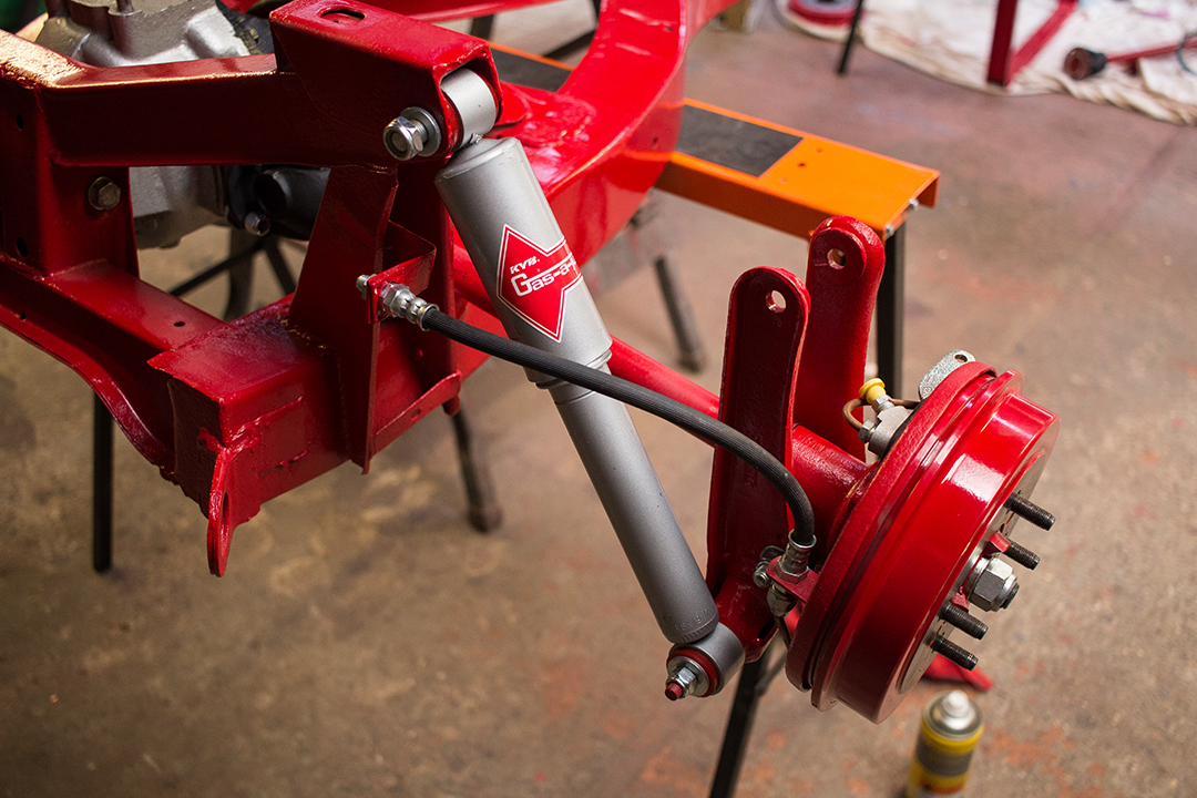
Now the dampers and driveshafts were in along with the vertical links and rear brakes. I fitted a new handbrake cable and hardware and new brake hoses.
Trailing arms are straight forward to install as long as you get them the right way round. New poly bushes and bolts of course…
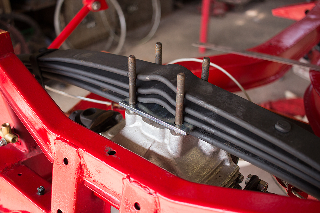
I sandblasted the rear spring mounting hardware and zinc plated it which seemed a better alternative to painting it. With that done I bolted the new spring in. The spring was a bit tough to get in but I got there with some help. It just needs raising a couple of inches which is harder than it sounds without the trailing arms mounted to the body. I had to prize it open to get the mounting plate in.
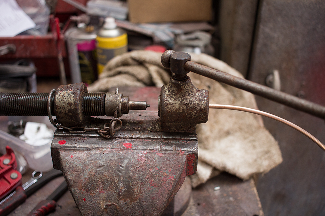
Now I moved on to the brake lines. I had originally intended to use plain old copper. Easy to form, doesn’t corrode. I started researching it a bit and discovered that it can work harden and crack and is even illegal in some countries. I can’t ever say I’ve experienced that but I’ve not replaced a huge amount of brake lines. I have replaced a few MOT failure steel pipes with copper in the past—no problem. Still, at this stage, I have the benefit of having access to a bare chassis so I went with cupronickel. It’s a tad harder to work with but it doesn’t work harden as easily and it stays brighter. It’s about the same cost as copper.
I used a little pipe bender and a vice mounted flaring tool and managed to get it reasonably neat. The flaring tool I used is an old one but it does a good job. No doubt it’s better than some of the cheap ones you can buy.

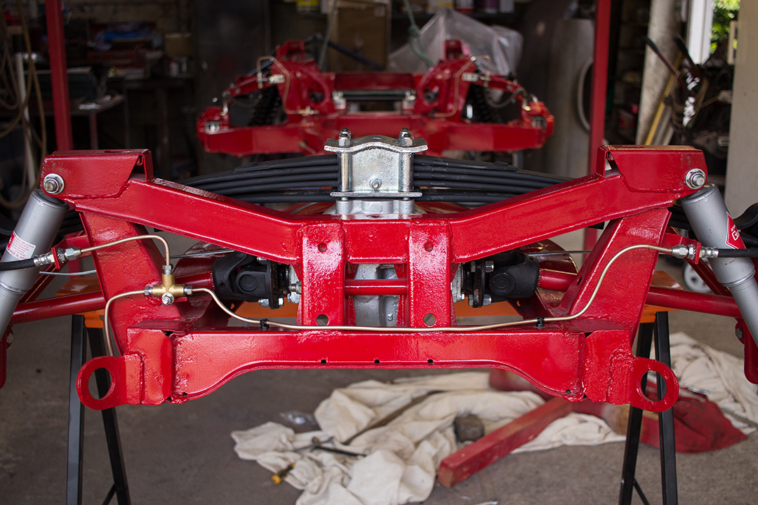
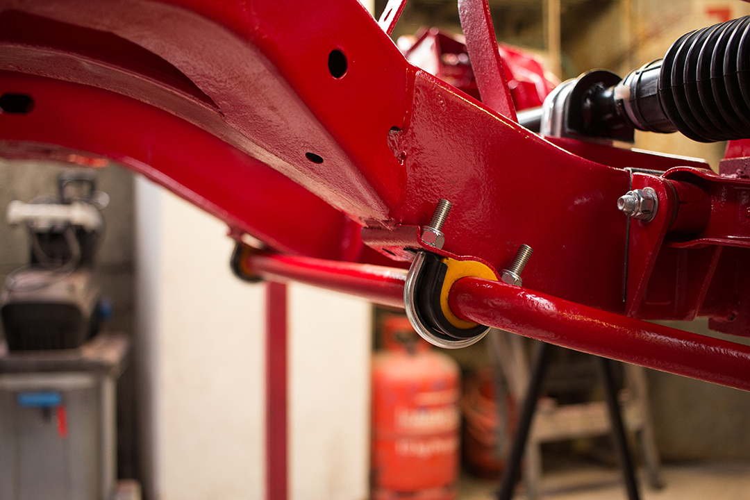
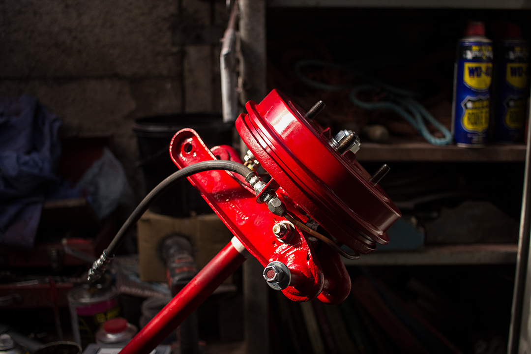
I decided to take a slightly different route with the front line. Normally it goes around the front of the off-side suspension turret, over the top and into the flexible hose. I preferred to run it under the suspension turret and up the side—just as it is on the near-side. It’s a neater and more direct route. That does mean that it’s going to be close to the exhaust on the chassis rail but I’m intending to wrap the exhaust with insulation anyway.
After so many hours of dirty work on the body with the grinding, cutting and welding sheet metal—painting the chassis and running gear was quite a quick job with a great deal of satisfaction. It looks so much better than it did when I took it off the road and made me realise how bad it had got with surface rust creeping in everywhere. It’s going to be tricky to keep it that way. At least now I’m confident I could respray or replate anything that requires it.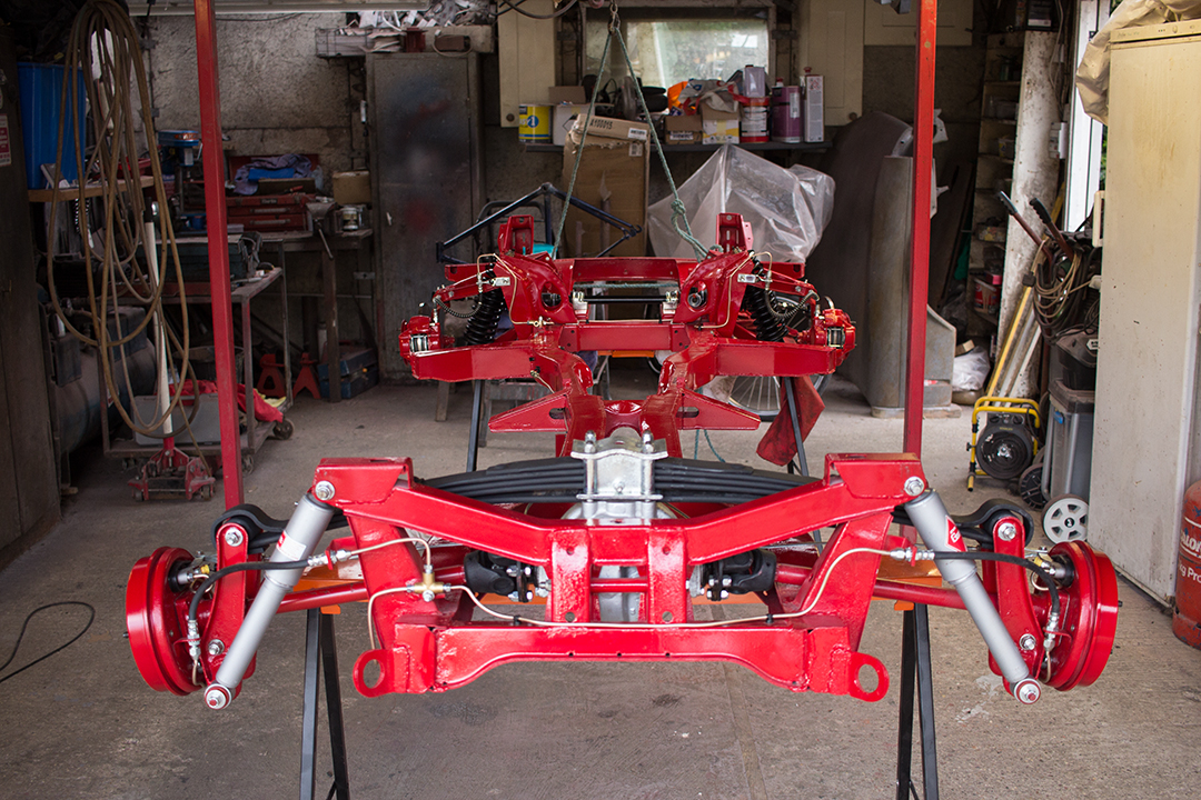
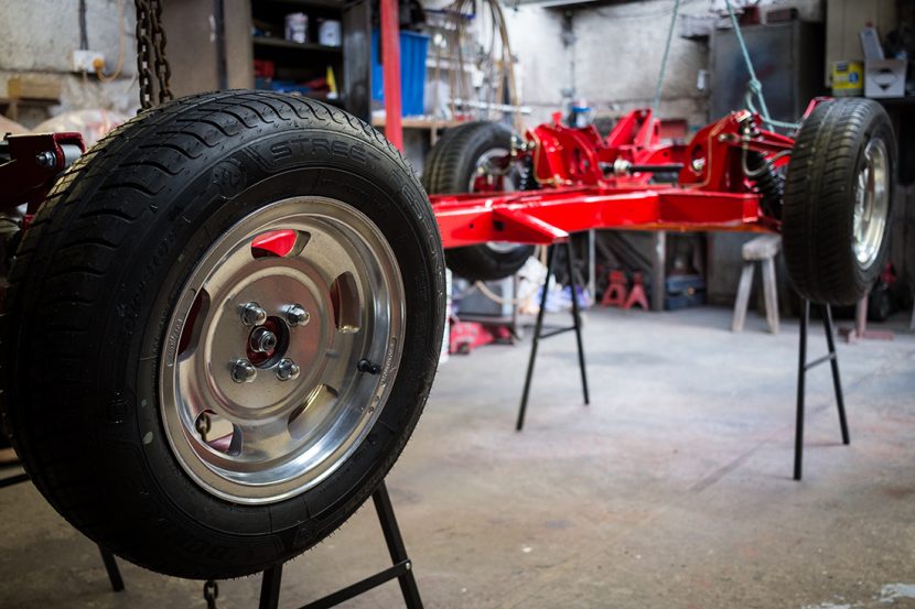
The final task was to get the wheels ready. I sold the old wires that were on it when I bought the car. They really did look the part but they were starting to corrode and lose the chrome plating. The offset wasn’t right either so low-speed steering was heavy and they used to catch the arches. That meant increased load on those poor little stub axles too. I have a set of Wolfrace Slot Mags for it now. I’ve had them for a few years and polished them up reasonably well. The slots were hand-painted red originally which doesn’t really sit well with my preference for the understated so I decided to paint them silver inside the slots and round the back to try and keep corrosion down and make them easier to keep clean.
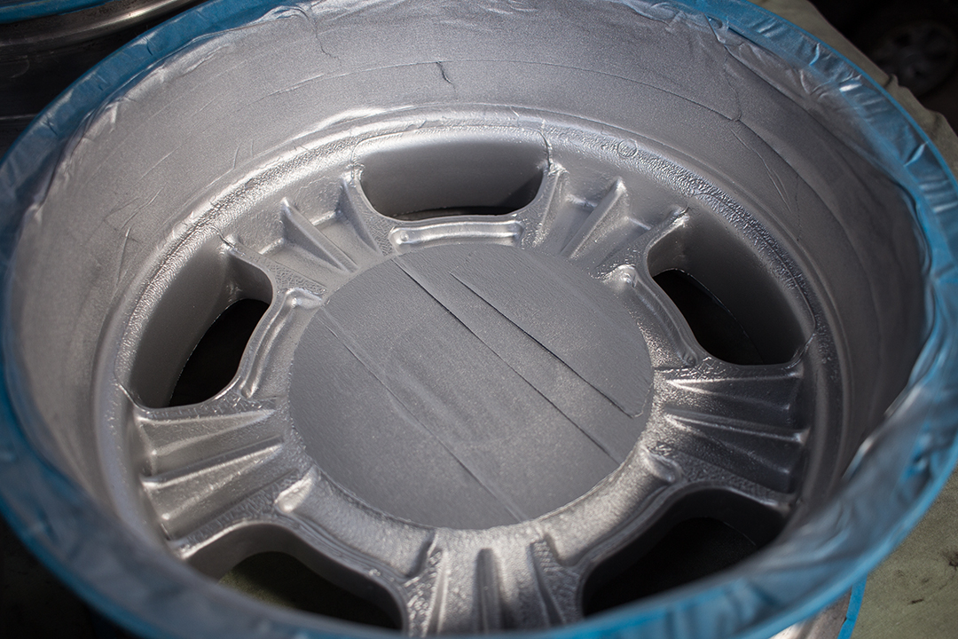
I masked them off and carefully cut the slots out with a Stanley knife blade. I primed them and sanded them ready for basecoat and lacquer.
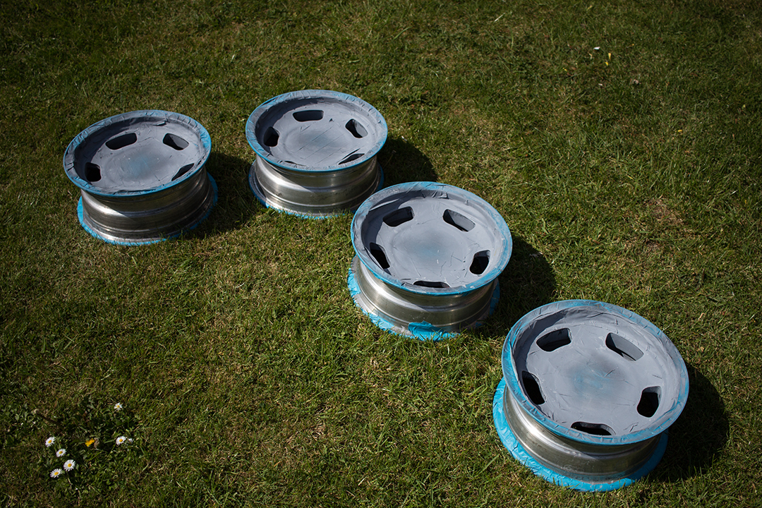
Basecoat applied and they are ready for some lacquer. It’s really tricky getting good coverage in those slots with a spray gun. No wonder they just hand-painted them originally…
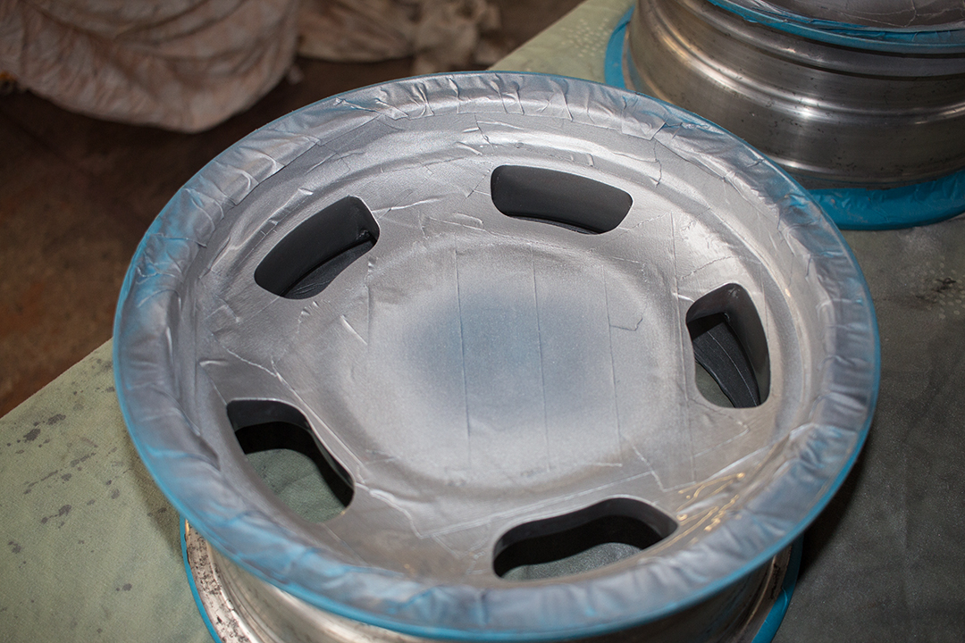
I have to admit, it wasn’t my finest work. I had a couple of runs in the lacquer in places and I didn’t get enough basecoat on in a couple of areas. Still, the result was much better than they were originally and I’m happy with them on the whole. I know there’s enough lacquer on there to provide good protection from brake dust and oxidisation. They should look the part when they are all polished up on the car anyway.
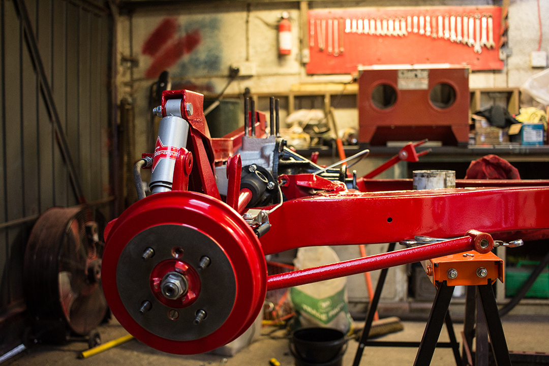
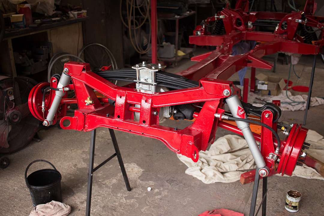
With the wheels done and now the tyres fitted and balanced I bolted them on and lowered the chassis. Finally, it was on the ground and rolling.


I topped the diff oil up and that was it, a rolling chassis. Now it’s back on to the body to get it ready for top coat. It looks great and I’m very pleased with it. I hope I can do the rest of the car justice too.