The Golf was suffering from yet more issues recently in the form of a worn turbo. This became apparent when a whirring sound could be heard when accelerating. I decided to replace the CHRA unit which is basically the core working part of the turbo and the vacuum actuator while I’m there. I thought it would be best to do it sooner rather than later as I didn’t want it to wear to the point that the impeller blades were damaging the outer part of the turbo which, in this case, happens to be part of the exhaust manifold on the exhaust side.
The procedure is quite straight forward but it is time consuming and can be very awkward because you have to work on the car from the top and underneath. The first step is to take off the engine cover and the air pipe that supplies the EGR valve.
Next is the EGR valve itself. This has 3 bolts securing it to the inlet manifold and is also connected to the exhaust manifold (or in my case the EGR cooler). There are a couple of small rubber hoses that pull off too. I found the EGR valve the trickiest part to take off pretty much!
Next is the inlet manifold. There’s 6 bolts for this which are a bit tricky to get at but it is possible even with an EGR cooler fitted. There are two bolts securing the plastic air pipe from the turbo, remove these. Once the inlet manifold is off you should be able to unbolt the EGR cooler from it and the exhaust manifold and push that out the way. My inlet manifold was absolutely caked in carbon deposits. I used Mr Muscle on it for several hours and managed to get the majority of it off but there was some still left. I jet washed it afterwards to make sure no loose carbon deposits remained.
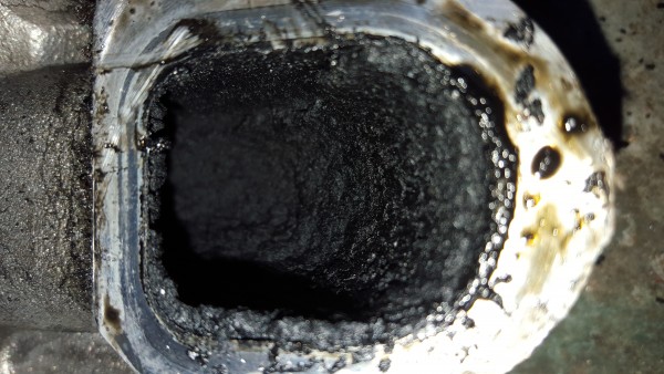
If the EGR valve is covered in carbon I would clean that up too but I wouldn’t use Mr Muscle on it. The sodium hydroxide in oven cleaner is supposed to eat alloys but I couldn’t see any evidence of this on the inlet manifold despite it soaking for several hours.
Next is the exhaust manifold and the turbo itself. First the oil feed pipe needs removing from the turbo. The fitting on the top of the turbo is a threaded union. The oil feed pipe has two supporting brackets, one on the exhaust manifold, the other is at the side of the engine near the tandem pump. Under the oil filter at the front of the engine is the other end. You’ll need to save the banjo bolt and copper washers from there.
I replaced mine with a steel braided type hose instead of the rigid steel one that was fitted. It may have been fine to use the old pipe but without removing it there’s no way of telling if it is blocked which may have been the route cause of the turbo wearing.
Next it’s on to the underside of the car. Obviously the car will need to be supported on axle stands. On the outlet of the air side on the turbo is a flexible hose. This can be removed just by popping the clips off and pulling it out. The air inlet side of the turbo needs a pair of grips to release the clamp. The plastic pipe from the airbox can now be removed from up top.
At this point I would remove the 8 nuts that secure the exhaust manifold to the head. It makes removing the exhaust pipe and various other parts a bit easier as the manifold/turbo assembly can be moved around. Make sure you have the socket on square for these bolts as they can be pretty welded on from the heat.
The oil return feed and support bracket can be unbolted from the block just beneath the turbo under the car. The lower two nuts securing the exhaust pipe can be removed from here too. The third and final nut for the exhaust can be removed from the top and the exhaust can be moved out the way. The whole exhaust manifold and turbo can now be removed. It’s a bit tight and you’ll have to wrestle it out without damaging the mating faces on the cylinder head and manifold.
The worn core unit needs removing next. This is the basis of the turbo so it’s more a case of removing the two air and exhaust sides from it. First remove the actuator by removing the circlip and the two nuts. Also remove the oil return pipe by removing two bolts. Before removing the compressor and turbine sides of the turbo, make note of where the outlet of the compressor side lines up as it is possible to put this back in the wrong orientation.
Remove 10 bolts that secure both the compressor and turbine sides. These have washers and clamp the core unit in to place. If it’s anything like mine you’ll be left with the turbine side stuck from corrosion and heat.
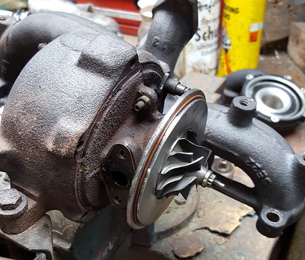
I gently heated the turbine side evenly and tapped it with a hammer, eventually the core came out. The old core wasn’t actually in as poor condition as I thought it was but the shaft was clearly more worn than the replacement. Better to replace it before any damage was done to the other parts. The turbo shaft actually sits on a cushion of oil while it’s running so there will be a slight bit of play in it but not much. This is why it’s a good idea to let the car idle for a few moments after driving it hard as the oil that feeds the turbo has the effect of cooling it.
The next bit is what made me need a second day to finish the job. On the turbine side are the VNT (Variable-Nozzle Turbine) vanes. These are rotated by the vacuum actuator on the outside of the turbo and control the velocity of the exhaust gas hitting the turbine wheel. At low engine speeds this means they are narrow to keep the exhaust velocity up and obtain boost. At high engine speeds they are opened up so the turbo doesn’t run too quickly and there isn’t too much exhaust back pressure.
There are 3 small M4 bolts that hold the vanes and the ring that operates them in. I successfully removed two but the third one sheared off. My dad and I spent much of the afternoon carefully drilling it out. Eventually it was out and I was able to save enough thread to replace the bolt. The vanes can all be cleaned up and put back in place. Mine were not too bad but apparently they can get completely stuck. One reason to drive the car hard now and then and keep the vanes moving!
It can be a bit tricky to get all the vanes, ring and retaining rollers all in place at once. I just worked round in circles knocking each vane in to place with a small screwdriver and pressing down on the ring at the same time.
The new core unit can be fitted now which is basically the reverse of removal paying attention to orientation. The actuator can also be fitted. This means that the rod length of the actuator needs setting which is usually done with a vacuum meter. I did mine by adjusting the VNT stop screw to the same position as the old unit and the rod length to the same as the old actuator. Having had the car back on the road it feels just as it did before so I’m confident that this is close enough. Unless the actuator and/or replacement core unit are drastically different then I don’t think there’s a problem.
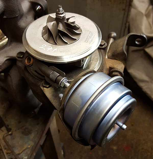
The oil return pipe can be re-fitted with a new gasket. You should then have something that looks like this which means it’s ready to go back in the car!
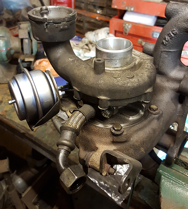
Refitting is more straight forward than removal. Don’t forget to prime the turbo with some oil. My replacement core came with a syringe that I used about three times to make sure the turbo wasn’t going to run dry before the new oil feed pipe was supplying it.
Having driven the car for a few hundred miles now I can say I have noticed an increase in power and the turbo is much quieter and smoother. Much of the power loss I would have put down to the clogged up intake manifold though!
Hopefully that’s it for now on the Golf and I can concentrate on the Spitfire. I hadn’t done a turbo until now so it has been quite interesting. Overall it’s actually quite an easy job technically but it just takes time because it’s not very easy to access.
Update:
I had a fault appear while driving again recently. This time I got “Emissions Workshop” on the dashboard and the EML. I thought this could be something to do with the recent work. I got home and scanned it with VCDS. Turns out it’s the coolant temperature sensor which has an intermittent fault. I think that would explain why the car wasn’t always starting well recently, without the coolant temp the ECU can’t decide how much fuel to squirt in when it’s cold. I’ll just replace the sensor as it’s only a few quid.
While I had the laptop connected though I thought I’d test the turbo boost. This can be done with VCDS. Go in to Engine – > Measuring Blocks. Set the block to 11 and start logging. Drive the car hard in 3rd gear above 3000RPM and check the log when you are done.
In measuring block 11 there are two values which will indicate that the VNT actuator has been setup correctly, one is specified intake pressure, the other is actual intake pressure. Above 3000RPM these should be roughly the same. If you have Excel or similar you can plot a graph and see how well the curves match…
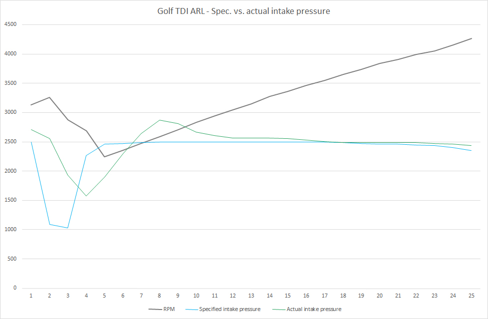
You can see where there’s some delay between the specified intake pressure and the actual intake pressure, that’s fairly normal turbo lag. You can also see where the actual intake pressure has overshot the specified pressure but then it remains pretty close, particularly above the 3000RPM mark. This means the VNT actuator is about spot on because the turbo is providing the correct amount of boost where it’s needed. Mine has peaked at about 2800 mBar that’s about 1.8 bar (26psi) boost pressure when you subtract 1 bar for atmospheric pressure and about 20psi maintained beyond that point.
All in all, that’s some peace of mind concerning the VNT actuator. Now I just need a new temp sensor…