I should really get into the habit of posting more frequently than every two years. My goal for the Spitfire for 2025 was to get the engine running on fuel injection. I have been busy throughout the year behind the scenes, working on my new Power Distribution Module (PDM) and changing the way the fuel system is set up. This time the PDM has 14 channels and runs all the circuits in the car. It’s now at the point where I can configure each channel, set the current limit, pair channels, and it deals with overcurrent faults. I can also override channels manually, so the first test—prime the fuel system which is configured as so:
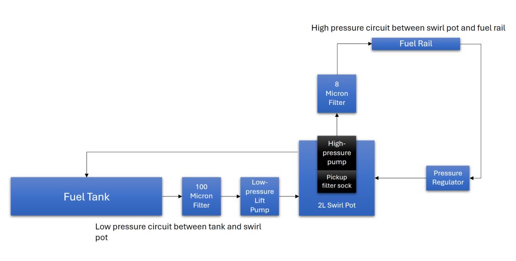
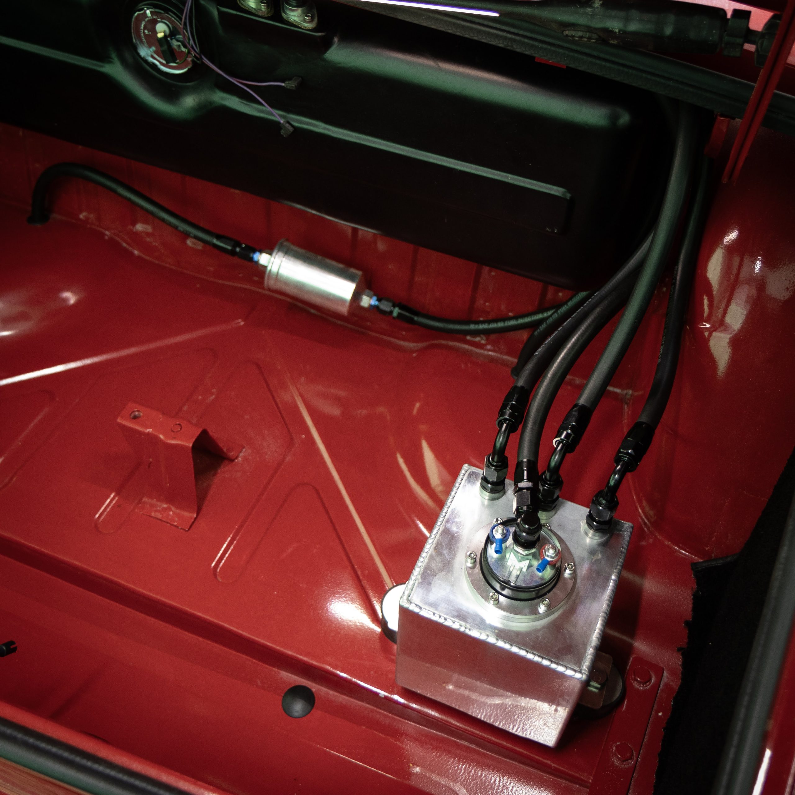
I realised that the high pressure pump I was using wasn’t self priming so I added the low pressure, self-priming pump and the swirl pot. This does mean that the baffles in the fuel tank aren’t really needed but the feed and return were in any case. I also have a fuel cooler which I haven’t fitted for now. If fuel temperature becomes a problem, I can put that in after the pressure regulator. With the pump being the submersible type (and inside the swirl pot), I expect that should keep it cool. Since I don’t have any experience with this stuff, it’s largely trial and error at this point.

Last time fuel was flowing, I nearly set the whole car on fire. Pretty sure my plastic garage would have gone with it. Possibly the shed as well. No idea what the fire brigade response time is here and I’d rather not find out so this time, I have a powder fire extinguisher, a CO2 fire extinguisher, fire blanket and the hose pipe all at the ready. My partner and daughter were away one weekend in November which gave me a couple of days of testing. The plan was to just test the fuel system for leaks, make sure the pumps are doing the job and, assuming that was all okay, set the fuel rail pressure. I thought I may as well check all my sensor inputs to the ECU while I’m at it. I wired that in a few weeks ago so it should be ready to go. If that really all goes swimmingly (I wasn’t overly optimistic), I could try turning it over to see if it will fire up. After all, I do know that it’s sound mechanically, having had it running on carbs and electronic ignition, albeit for a brief period before I was giving Keith Flint a run for his money.
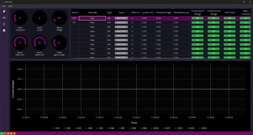
I configured the PDM according to the wiring in the car and the plan I’d made for each circuit, set the current limits to an educated guess and connected it up. I’ve written the desktop software to configure the PDM in C#.NET with Avalonia UI. My limited experience as a C#.NET developer was all in WinForms. I didn’t find it too challenging to learn AXAML (XAML), the resulting application looks half decent and will be cross platform (Windows, Linux & Mac OS). I doubt it’s really very well optimised at this stage. The live data view isn’t always as responsive as I’d like but being XAML/WPF based, everything seems to scale nicely on different resolution screens and the built in controls are nice. Full details of the open-source controller and the config utility are on my Wiki. Here’s the live data view:
I checked all the loose wiring in the car to make sure nothing was going to short and powered the PDM. Power up, all good. Disconnect and check the fuel system. I had a look around the car just to check that I hadn’t forgotten to tighten a clamp or something up. All seemed to be well, so I proceeded to put 20 litres of stabilised fuel in the tank and check for leaks. No leaks.
Now I powered the PDM up again and ran the low pressure/lift pump. It ran well and I could hear fuel flowing into the swirl pot. The current reading of the fuel pump on the display was quite erratic, mostly due to the nature of the pump because it pulses to maintain pressure. I then ran the high pressure fuel pump and discovered a couple of small leaks, easily rectified by tightening a jubilee clip and applying some PTFE tape to the pressure gauge thread. The issue with the high pressure pump was it was reading way over current, 50A. I scoped the current with my current probe and found it closer to 5A continuous. The same issue applies to the high pressure pump in that it pulses to maintain pressure but in this case, I think it’s much more inductive so the current reading is inaccurate. The PDM simply takes an average and applies a calculation to read current in amps. I think what I may need to do is take a median value and apply some more filtering such as an exponential filter. It may be that a snubber or something is needed at the pump to dampen those inductive spikes seen back at the PDM. The goal will be to balance overcurrent response time with accurate and stable current readings. I suspected I’d either be spending some time on my laptop next to the car or I’d need to setup some sort of bench test to replicate the pump.
I got the PDM back on the bench and went to solder some enamelled wire to the HSD for the high pressure pump to connect the oscilloscope, and there it was, a solder bridge between the enable and current sense pins. I re-tested and it worked fine. No code changes or test rigs required so that was some time saved. I got on with setting the fuel pressure and connecting to my ECU. I turned the engine over at this point to check signals to the ECU, not quite right. I had to start a new Tuner Studio project and re-configure the ECU again. I couldn’t remember where I’d got to with the tune that I’d loaded over a year ago.
I connected up again and tried to start the engine. Misfiring and backfiring. I couldn’t figure out what was going on so a started systematically checking everything. Broke a plug. Replaced plug and carried on. Broke a plug cap. Ok, this wasn’t going to plan and I’d spent pretty much a whole Saturday messing about with it now. What a waste of a day. I thought about it that evening and realised that I’d replaced a plug with a non-resistor type. That was a problem and explains the sync loss I was seeing on my ECU. Non-resistor plugs don’t get on well with sensitive electronics. I also realised that evening, that I’d got my injectors wired in the wrong way for sequential injection. The ECU will pulse the outputs in numerical order, 1-2-3-4, but the firing order is 1-3-4-2. Frustrating but at least there was a credible explanation for why things weren’t working. I had tried semi-sequential at one point which would have worked but by that stage, I’d already replaced the plug with the non-resistor type and was getting sync issues. I struggle with days like this. Time is precious and I felt like an idiot. Re-group, try again.
I rewired the injectors, double checked everything and had another go. This time, it fired up. I was elated! Two year’s work seemed to have finally paid off. Running on three at the time, though, so something still not quite right. I took the rocker cover off to check the valve train, couldn’t see anything obvious so I did a compression test, nothing on 4. Turns out the valve clearance on the inlet valve was non-existent, meaning the inlet valve never closed through the cycle and hence no compression. I adjusted that and tried again, running on all four now, excellent. You can see it running below.
It was idling quite fast, around 2500RPM. I suspect this is probably the vacuum tubing leaking since each runner is linked to a manifold which is linked to the fuel pressure regulator and the ECU MAP sensor. I think I’ll remove this for now, see if my idle comes down and just set the car up using throttle position only. The Juice Box 2 ECU I developed in 2023 is pretty much redundant now already since the Teensy 3.5 microcontroller it’s based on is end of life. The Juice Box 3 is in development and this time is STM32 based. STM have long term commitments to manufacturing their processors so this is a safer bet. It’ll have a few new features including a built in wideband O2 sensor controller and PWM stepper control so I can add an Idle Air Control Valve (IACV) down the line if I need it. This allows closed-loop control of the idle speed by controlling auxiliary air flow into the inlet runners. I think, between closed loop fuel mixture control with the O2 sensor, inlet air temperature and barometric corrections from the on-board barometric sensor, I can get the car running 90% of the way I’d want it to on throttle position alone, rather than a mix of that and manifold pressure.
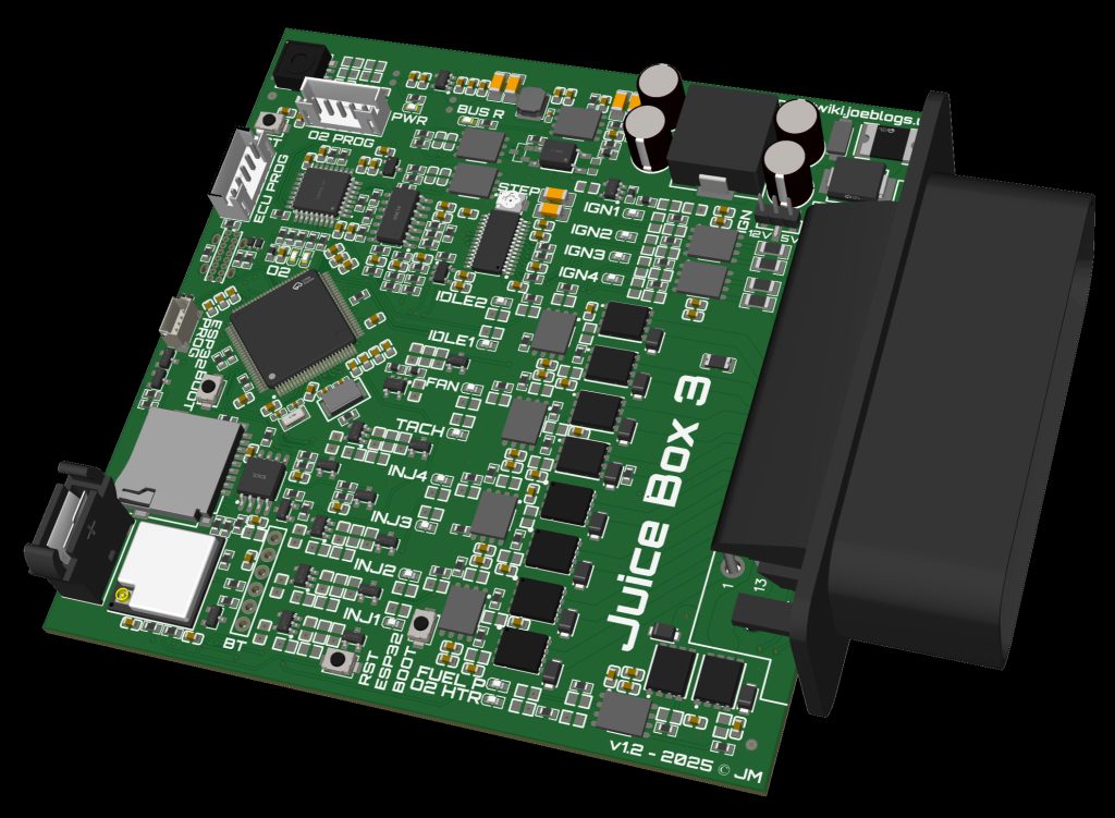
When JB3 is ready, I’ll rewire a few of the sensors with 3-core shielded cable and remove the vacuum tubing and setup the Throttle Position Sensor (TPS) for maximum resolution, trying to use the full 5V range. Throttle position is very sensitive near the close position. A small increase in opening results in quite a big change in air flow and this reduces as the throttle is opened wider. The difference between closed and 5% is very big compared to the difference between 95% and 100%, effectively nothing. This means resolution and noise are important. The main aim is to get it running well enough for drivability and so it passes an MOT. Tuning can be done when the engine is properly run in and the car is on the road. I also need to characterise the coolant temperature sensor and make sure that is reading correctly on the ECU as that will have quite a big effect on the fuelling. The PDM performed well once I’d got the resistor plugs back in. The sleep/wake function was a bit off still, fuel pumps running on when they weren’t mean to so I think the firmware needs to be a bit more robust around when to enter and exit sleep. It’s currently done off an interrupt linked to the ignition input. This probably just needs validating in either state after 100ms or something to ensure it’s not bouncing or falsely triggering. The IMU also fires an interrupt to wake the controller so that may need a timeout after ignition off before it’s armed as well.
That’s about it for the time being. Getting the engine started on EFI has really given me some more drive to get on with it. I’m also happy with the fuel system and wiring so I can start putting some of the trim and carpet in when the weather warms up a bit. Watch this space.