Well, it’s over 2 years since I made a post. Quite a few events have happened in that time, some of which have changed my life forever. Sadly my father passed away in February this year. I owe him so much for being the inspiration behind a lot of what I post about here. He was an engineer of many sorts but had a lifelong passion for electronics and motor mechanics which I’ve inherited and learned most about from him. With him in mind, I want to press on with what I’m trying to achieve with the car. This one is for you, Dad.
On the positive side, our first child—a daughter, was also born in April. She’s an amazing little person to have in my life and brings us a lot of joy. I’m sure she’ll be bored to tears when I’m recollecting my engineering stories when she’s older! I can’t wait until she’s old enough to enjoy being a passenger in my Spitfire.
Having developed the JuiceBox ECU in 2020, I put it to the test last year. It worked well and I started the engine for the first time since the rebuild but I had some noise issues and erratic timing. I used a smart coil that has built-in IGBT drivers that should prevent back EMF from reaching the ECU but something was amiss. Eventually with some research and proper testing, I settled on a separate IGBT control circuit and traditional ‘dumb’ coil pack.
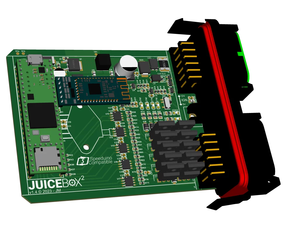
For the engine management side, I decided to design a new ECU that would allow me to move to fully sequential injection. The enclosure is a transparent Deutsch type that’s used on many ECU-type applications. The connectors carry reasonable current and they are sealed.
I removed the VR conditioner IC because I had already moved to a quality hall-effect sensor for crank angle. CAN bus now features as standard and will allow my 52mm Smiths instrument display which I’ve converted to house an LCD. CAN is handy to have down the line for adding additional sensors or control of the ECU from other sources. The display has a capacitive touch controller that is connected to the housing so you just tap the bezel to cycle through displays and receives data from the ECU using the standard OBD II protocol.
I got the ECU assembled and bench-tested it as far as I could. Everything was looking good. I connected the bare necessities to the car, crank angle sensor, power, coil pack and MAP sensor. I turned the engine over and checked the software on the laptop, no sync loss and the ignition LEDs looked to be firing consistently. Now we’re talking.
I filled my temporary fuel can and gave it a bit of choke, cranked it over and it fired up. Keeping the revs up at about 2500 RPM to try and bed the cam in successfully, I got through that small bit of fuel I’d put in the can in short order so I refilled it and tried again. Running for a good ten minutes, everything worked beautifully until the radiator cap saw 13 PSI and the overflow tube was spraying hot coolant out onto the drive. At this stage, I didn’t have a fan fitted and it hadn’t occurred to me how quickly it would overheat. Rookie error. At least I knew my re-assembly of the engine must have been done correctly, at least for the initial test.
A few moments later I saw some fuel leaking out of the carbs followed by a ball of flame. The temporary fuel supply tube had melted through onto the piping hot exhaust manifold and gone up in flames. I ran for the fire extinguisher but it went up again, I used a second one and finally the garden hose. It went out and I had to talk myself through what had just happened. The carbs were pretty crispy. The jet tubes had melted through, adding more fuel to the fire and the bulkhead had suffered some damage.
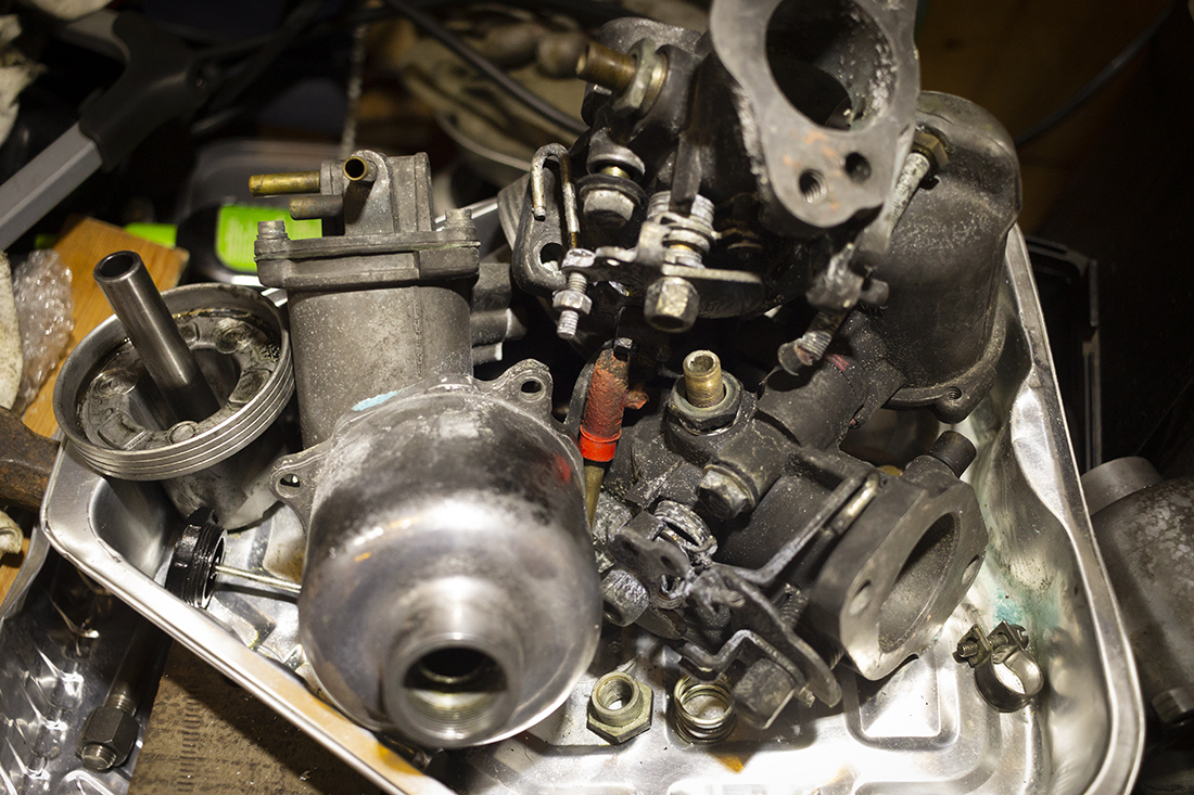
It could have been much worse though. The damage to the bulkhead should be fairly easily repaired. The damage to the carbs got me thinking more seriously about injection, however, so I did some research and bought some Kawasaki ZX6R throttle bodies complete with throttle position sensor and injectors. My journey of going to full EFI had begun.
Several months passed while I was working on other parts of the car. I initially tried an isolated approach with ECU, putting the processor behind isolated drivers and op-amps. Around this time the chip shortage went into full swing so I decided to design, yet another, new ECU version. I had to redesign the board using much more common component footprints and concentrated on designing a simple, low-noise board with robust filtering. I removed the galvanic isolation since it relied on sourcing expensive, galvanically isolated ICs and MOSFETs with proprietary footprints. I also added proper transient protection on the CAN interface and analogue inputs. For the power supply, I improved filtering and transient protection. I went with a SIG/GND/PWR/SIG, 4-layer stack-up on the PCB mainly to give all the signals a solid uninterrupted reference plane. Of course, now we’re almost in 2024 and things have changed since I designed this ECU. The Teensy 3.5 processor that I based my design on is no longer available. Good job I have a small supply of my own that I can use. I suspect I’ll be designing a new one using the Teensy 4.1 in the not-too-distant future, however.
Adding sequential injection means the ECU will expect a single-tooth cam signal which is used when first starting the engine to synchronise the timing. Once the timing is synchronised, the ECU will know where TDC for cylinder one is and injection timing occurs using the crank angle from the primary trigger. The only sensible place to get this cam position signal on a Spitfire engine is from the distributor drive so I plan to modify an old distributor to house another hall effect sensor and trigger wheel which will involve a bit of lathe work.
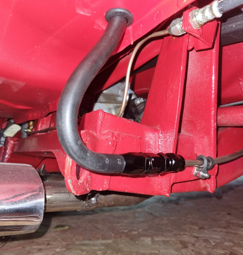
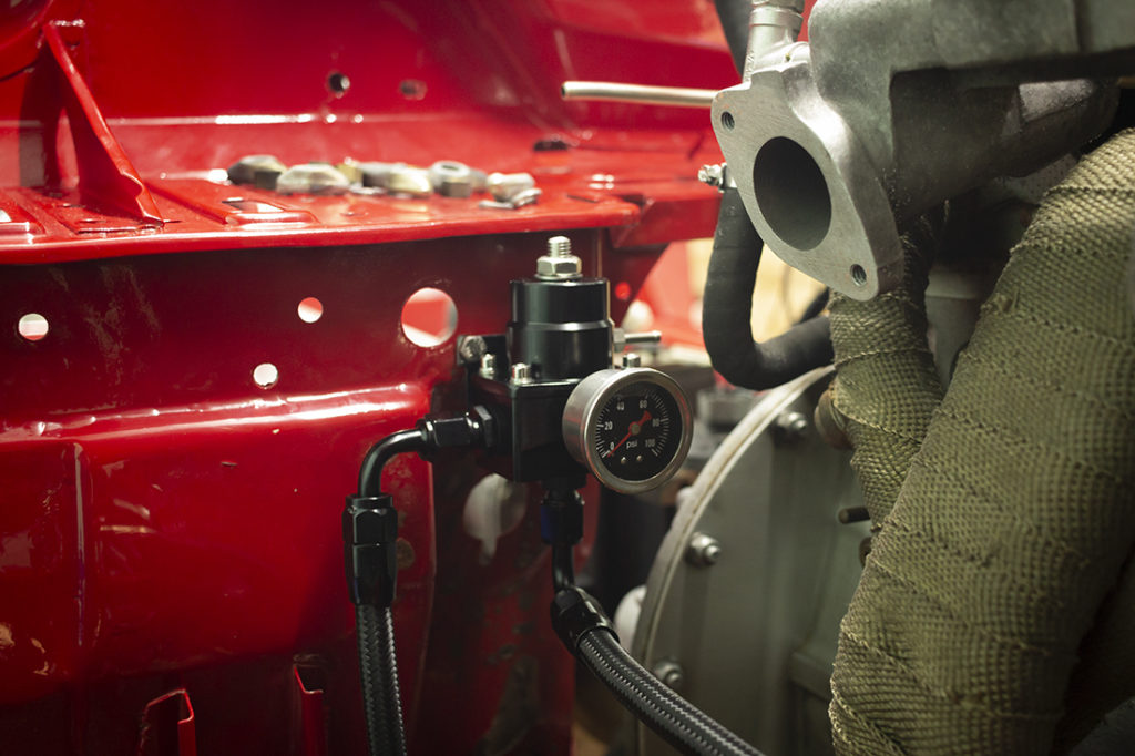
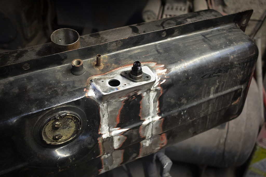
I started plumbing in the fuel lines next. The original line just went through the boot floor from the tank, down one of the chassis legs and fed the mechanical pump on the side of the engine. I used the same path for the feed line, except I extended it up and over the bulkhead to the inlet side of the engine where it would feed the injector rail. From the injector rail, the return line feeds into the regulator mounted on the bulkhead, from there down to another hard line that goes down the other chassis rail, back to the tank through the boot floor on the other side. I used 5/16 cupronickel for the hard lines which should be plenty big enough to feed my little Spitfire engine at 3 bar pressure.
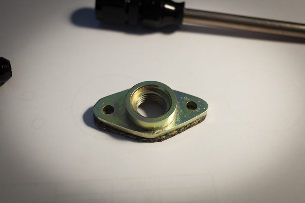
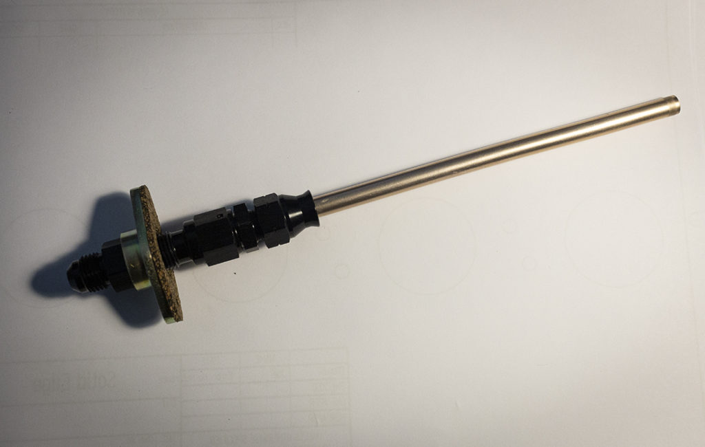
For the fuel tank, I decided to install some baffles. This would help fuel surge in cornering and prevent the need for a swirl pot. The Spitfire tank is pretty much the perfect shape for fuel to surge and cause starvation being a wide rectangular shape. This would mean cutting a hole in the side of the tank but then I could also make sure it was really clean inside. The baffled area near the centre would have both the feed and return pipe so that the return is always topping up the baffled area and a small hole in the bottom of the baffle to supply fresh fuel. I tuned two SAE O-Ring bosses on the lathe with 9/16-18 UNF threads to accept the 90° AN6 bulkhead adaptors I bought. Inside the tank, I could use 5/16″ cupronickel pipe with compression fittings.
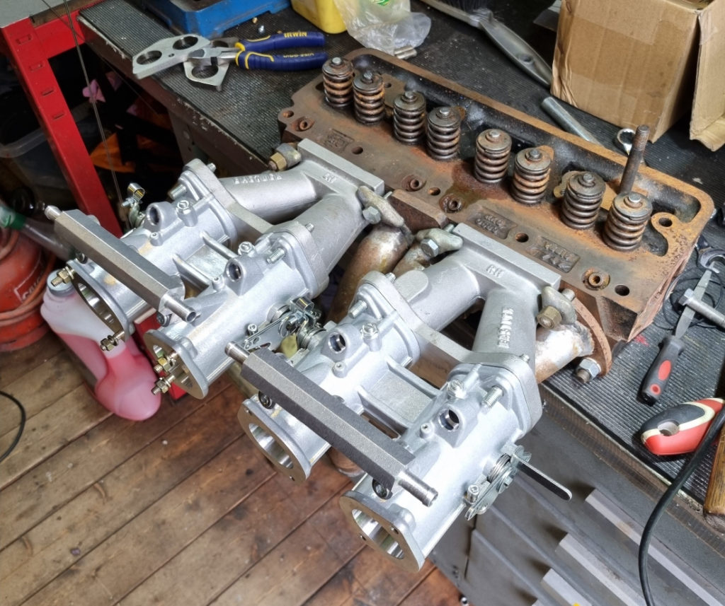
The most tricky part of converting the car to EFI was the inlet manifold. Initially, I was going to fabricate one from stainless but this would take some time and it’s quite a tall ask for someone who’s not done much TIG welding before. At this stage, I realised that I probably wasn’t going to drive the car again in my thirties and things were just taking too long. Spare time is not something that I have in abundance these days so progress would have to be made more efficiently if I was ever going to drive the damn thing again. I bit the bullet and bought some Weber DCOE manifolds and DCOE 40 throttle bodies. With a bit of fettling, I got them to fit nicely with my stainless branch exhaust manifold on a spare cylinder head I picked up for £5. I also took the opportunity to remove the existing head and check the condition of the bores since the engine hadn’t been started in so long. Everything looked fine. I just smeared some more engine oil around the bores and reassembled.
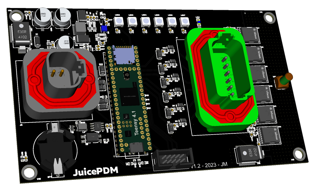
That’s pretty much where I’m at with the EFI conversion this year. Next year, I’m hoping to get it running again on full sequential injection. As the spring and summer roll around, I should be able to start doing a bit more in the evenings after the little one is in bed. I have managed to get a couple of other electronic projects to about 75% completion. The first is my Power Distribution Module. It has six configurable 13 amp channels, is CAN enabled and has features such as SD card logging and diagnostics. It will run things like my fuel pump and radiator fan. The hardware is about there. I’m just working on the firmware which needs more work in the current measurement area. Reading the current sense pin from a PWM-controlled high-side driver isn’t a trivial task and requires very accurate timing for ADC readings and subsequent calculations to give an accurate representation of the power being used. I’ll also need to build myself a much beefier power supply. My little 2A adjustable is fine for most stuff but to fully test this and properly characterise current readings throughout the entire range, I’ll need something that can produce at least 78A. I’m looking at 1000W switching supplies you can get on eBay to build a new supply. That would allow me to test all six channels hooked up to some high-wattage power resistors and check that everything is working within limits from a thermal standpoint. The high side drivers I have used are super low on resistance so they shouldn’t generate much heat and they have a large amount of copper and thermal vias to help dissipate what they do generate. Nothing is certain until they have been tested at full power, though.
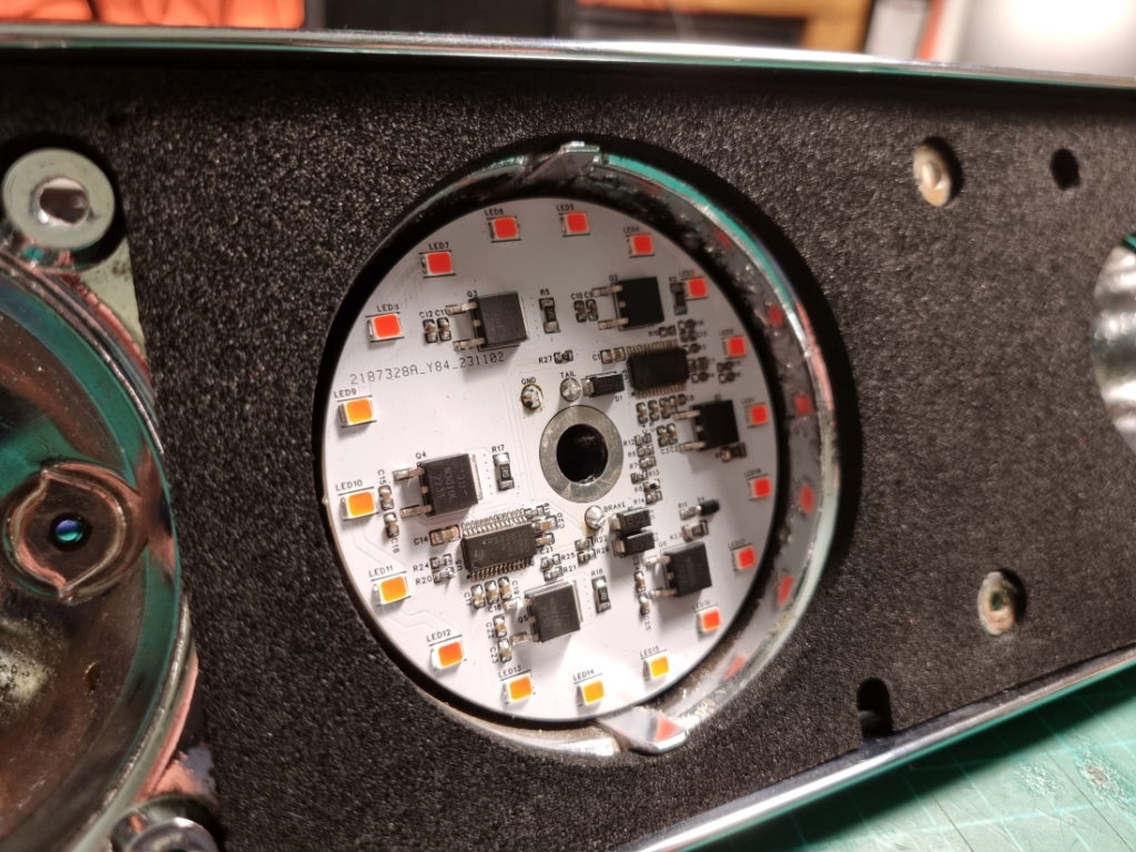
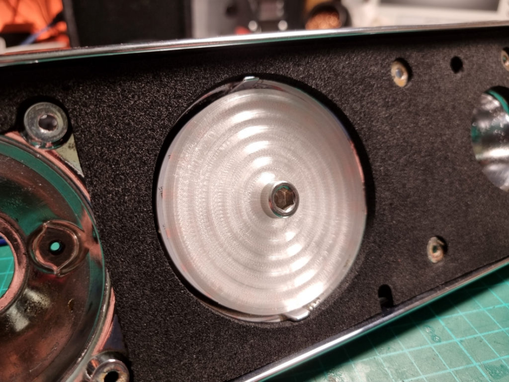
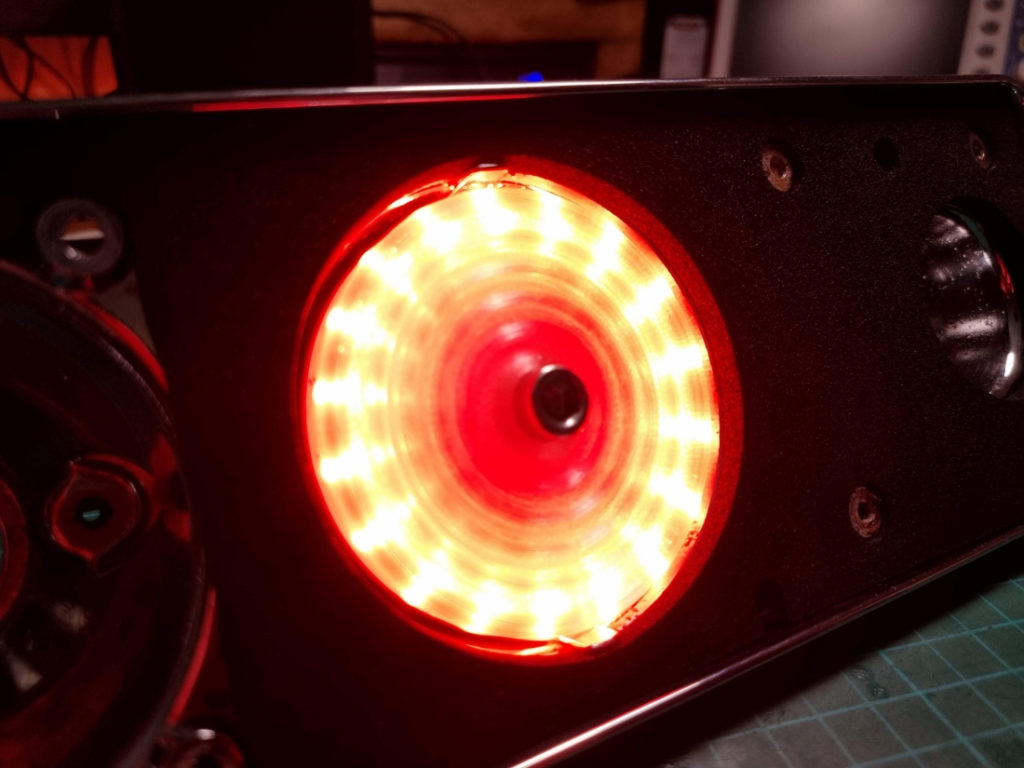
The second electronic project I’ve been working on is for the rear lights. These PWM controller LED modules fit in the rear light clusters and replace the terrible bulb holders. Based on a Texas Instruments reference design, they worked a treat, first time. I only needed to change a resistor out to lower the LED current a tad. Tail, brake and indicators will run on these neat little modules. With the help of some 3D printed parts to mount them and also to act as a diffuser, I think they should be quite a bit more reliable, and visible, than the old bulbs. I’ll just need to apply a conformal coating to the PCB as the light clusters aren’t all that well sealed.
Merry Christmas and Happy New Year to you all. I’ll be back in 2024 for the ever-ongoing Spitfire restoration. Will it ever be finished? One day…
5 thoughts on “New ECU & the Great Fire of ’22”
For a timing sync reference why not use the fuel pump lobe on the camshaft. A magnetic sensor mounted through the blanking plate you need when using a seperate efi fuel pump.
Possible, but two reasons. 1. I already have a nice machined aluminium blanking plate that a friend made for the fuel pump blank! 🙂
2. I can’t imagine a lobe is going to produce a very reliable, digital signal. Unless you can guarantee a repeatable threshold with the magnetic sensor? You could use it with a mechanical switch of some sort but then you’d have reliability issues.
I can feel you reluctance to put a hole in a nice shiny blanking plate !!
While a valve lobe and the fuel pump lobe are different shapes the use of a cam lobe to confirm which stroke of four a cylinder is on is actually quite common on modern engines. I think the fuel pump lobe should be tall enough to generate a very clear there or not signal.
I’ve added your blog to my reference info should I go efi with my own project.
Hello Joe,
I came across this project on OSHWLab; i think it’s a perfect fit for my resto-mod project I’m working on.
However, the most important impediment to getting this board made is that the Teenay 3.5 is EOL and hence bit available anymore.
Is there any plan to port this over to the Teensy 4.0 / STM32 Bluepill/Blackpill?
Also, on your blog, you list a PDM; is that yet bit ready for publication?
Thanks,
Madhu.
Hi Mahdu,
Yes, the Teensy 3.5 is definitely not a viable option now. I’ve no plans to redesign a new ECU just yet. There are quite a few Speeduino based ECUs out there though, you might find one that’s got more parts available.
The PDM project is taking up quite a bit of my time at the moment. I decided to add more channels so it will have 14 outputs, more inputs as well as analog inputs and will be STM32 based. I’d expect to have a beta version of that available later this year. Keep your eyes on my wiki/OSHW/GitHub pages for that.
Cheers.