I’ve spent quite a lot of time researching ignition systems for the Spitfire. Before I took it off the road for restoration, I had a basic electronic system that removed the points and added a high output coil. It did the job and was reliable. Since the points were probably worn I think it made for smoother running and a tiny bit of performance gain. This time, however, I want something that can be programmed to take full advantage of the modifications to the engine. A few options came up…
CSI ignition. A good halfway option in that the distributor has some electronics inside that allow you to choose from 16 different ignition advance curve presets. It’s nice and straight forward but you keep the distributor and it doesn’t give you a truly programmable ignition system.
123 Ignition. A step further to CSI in that it allows fully programmable advance curves, via Bluetooth with an app if you feel so inclined. It also allows you to program a rev limit and has an option for an anti-theft code. This is a solid option but still has the distributor and is around £300 before adding a coil and HT leads which put it up there with the cost of the next two options.
Nodiz. This does away with a mechanical distributor all together and replaces it with a fully programmable, Bluetooth enabled controller that works using crank position. It also has built-in coil drivers, built-in MAP sensor and a 16×16 ignition table. This is probably the pick of the bunch at £270 with a bare wiring loom. All you would need to buy on top of that would be a trigger wheel with sensor, coil pack and HT leads.
MegaJolt. Similar to the Nodiz unit except it’s been around longer and requires a few more parts to work. It is the most expensive, totalling about £400 for everything required for a Triumph Spitfire. It has several advantages in that it removes the need for a mechanical distributor by using a trigger wheel and crank position sensor, has a programmable 10×10 ignition advance table with linear interpolation and a built-in MAP sensor for engine load measurements. It also has several additional features such as a rev limiter and temperature sensor input to further fine-tune ignition timing as well as cranking advance and an option switch to flick between two saved ignition maps.
A newer version of the MegaJolt was announced in 2011. It would remove the EDIS unit, have coil drivers and VR sensor reading built-in, enabling the use of coil-on-plugs and claimed timing resolution to 0.1° through use of crank and cam position sensors. It was based on an ARM processor and had higher resolution timing as well as Bluetooth. The project was dropped though, sadly. The source code and hardware design are on their GitHub page but neither are finished and would require quite a bit of work to have a fully working system with configuration software.
I set to work and designed and built my own Megajolt since all the schematics and firmware are available. I even got the go-ahead to build my own from Autosport Labs owner, Brent Picasso, on the basis that he wouldn’t offer any support for my home-brewed version. Everything tested OK, the serial comms via Bluetooth was working. The main problem I had was programming the MCU. I realised that it was quite an old MCU but I found quite a few resources to program it. I tried 3 different circuits from NXP that I found in some of their own literature, specifically designed to program this type of chip but could not get any of them to work. In the end, I had to give up on the project because I’d literally tried everything to flash the controller. I’d resigned to the thought of just buying a Nodiz and using that until I found the Speeduino project.
I’m not sure how I hadn’t stumbled upon Speeduino before now given the amount of research I have done on the subject. It’s a completely open-source, Arduino based, engine management system. I quickly found that I could adapt it to work as a programmable ignition controller using common MCUs like the Arduino Mega, Teensy or STM. I set about making my own PCB design based on a Teensy 3.5 since the Teensy is lightning quick and small in size. Things have also progressed in terms of coil packs with many having built-in ignitors, all I’d need to do is provide some digital signals to drive one and I wouldn’t need an EDIS module.
The Speeduino also supports various sensors including throttle position, manifold pressure, inlet air temperature, coolant temperature, battery voltage, and an O2 sensor. Most of these wouldn’t play a part in controlling my ignition timing but could be useful for monitoring or tuning.
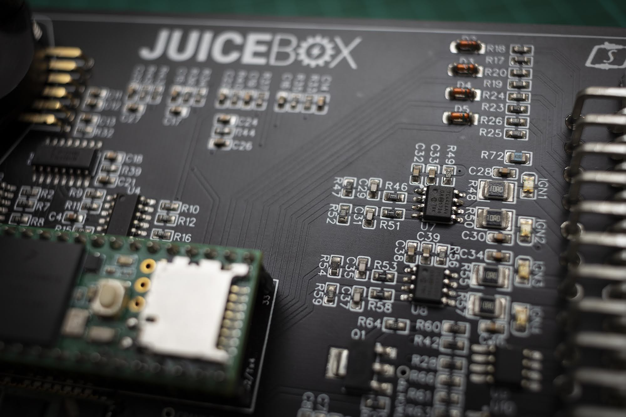
I started working on my design and came up with the “Juice Box”; a simple, Speeduino-based ignition controller.
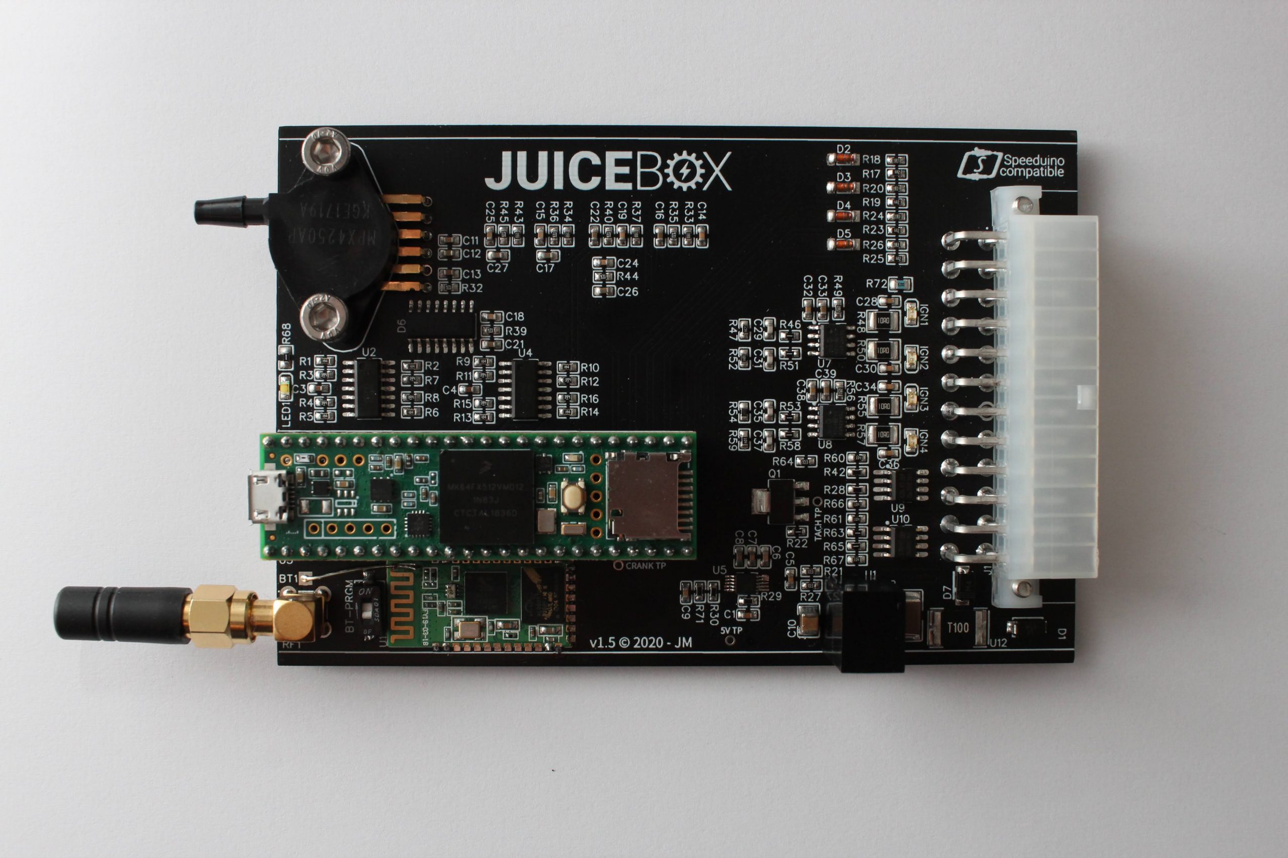
I excluded all the injection-related parts of the circuit and added a few more inputs and outputs. The power input has reverse-polarity protection, over-voltage protection and is fused which supplies a wide-range 8-36v input, high-efficiency voltage regulator so the board stays alive while cranking. I also added an onboard Bluetooth module with an external antenna connection. I used a 24-way Molex connector which is rated to 13 amps so the high current outputs should be good for 10A. The PCB measures 120mm x 80mm and is designed to fit in an aluminium extruded enclosure (a Hammond 1457 specifically). I tried various sizes and connectors. My main focus was to try and make it a robust board that will take some abuse, provide solid connections and keep the size down as well as include everything needed to for a complete ignition system on one PCB. I went with a VR sensor for the crank position because they are generally cheaper, more reliable and readily available. I could always connect a hall effect sensor to one of the general-purpose IO pins with minimal changes to the board and firmware.
I included in my IO:
- Ignition out (x4)
- VR crank sensor input
- Tacho output
- Manifold pressure input
- Coolant temp input
- Inlet air temp input
- Throttle position input
- O2 sensor input
- Fuel pump output
- Cooling fan output
- High current output (x2, general use)
- General-purpose digital inputs (x4)
- General-purpose analogue inputs (x2)
- 5V sensor reference
- 12V supply
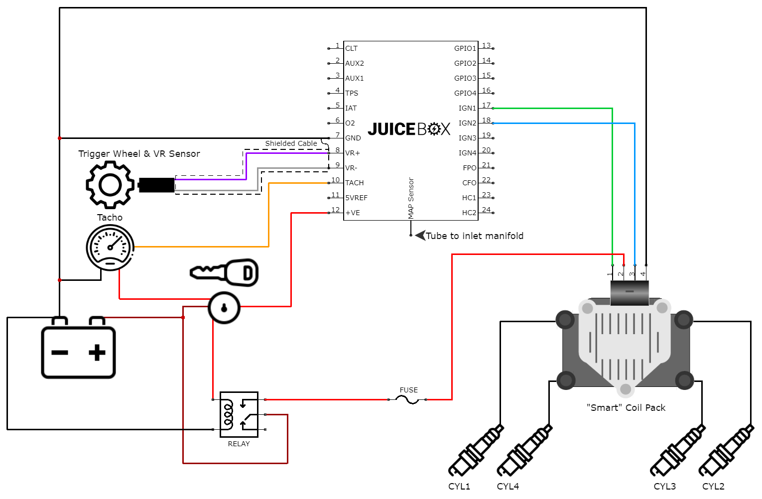
The basic setup would look like this:
The ignition table is comprised of engine RPM on one axis and engine load, in this case, manifold pressure, on the other. The result of these two inputs determines the ignition advance. This isn’t really any different to the original distributor which uses centrifugal weights and vacuum from the manifold to determine the ignition advance. Of course, the distributor is limited in the range of advance it can offer and relies on an outdated mechanical design. Modifying the advance curve involves adding or removing material from the weights.
With my additional inputs such as coolant temperature, I can configure an output to operate the cooling fan at a specific temperature and hysteresis range. I would plan to add oil pressure as an input too. It would be interesting to see if my baffled sump prevents any oil pressure drops.
The software used with Speeduino is Tuner Studio which is a free download although there are paid versions with more features. I made my design open-source, the schematics and PCB are available on EasyEDA. My fork of the firmware with associated pinout is available on my GitHub page. Just recently, my changes were merged back into the main project which means the Speeduino firmware will now support my board.
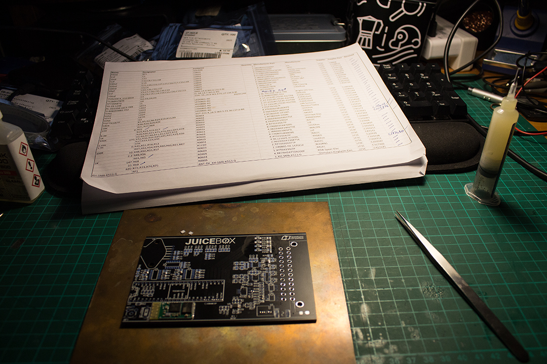
I was going to try JLC PCB on their PCB assembly this time around but just as I was ready to order, the Coronavirus hit and JLC PCB went into minimum service so I had to assemble it myself.
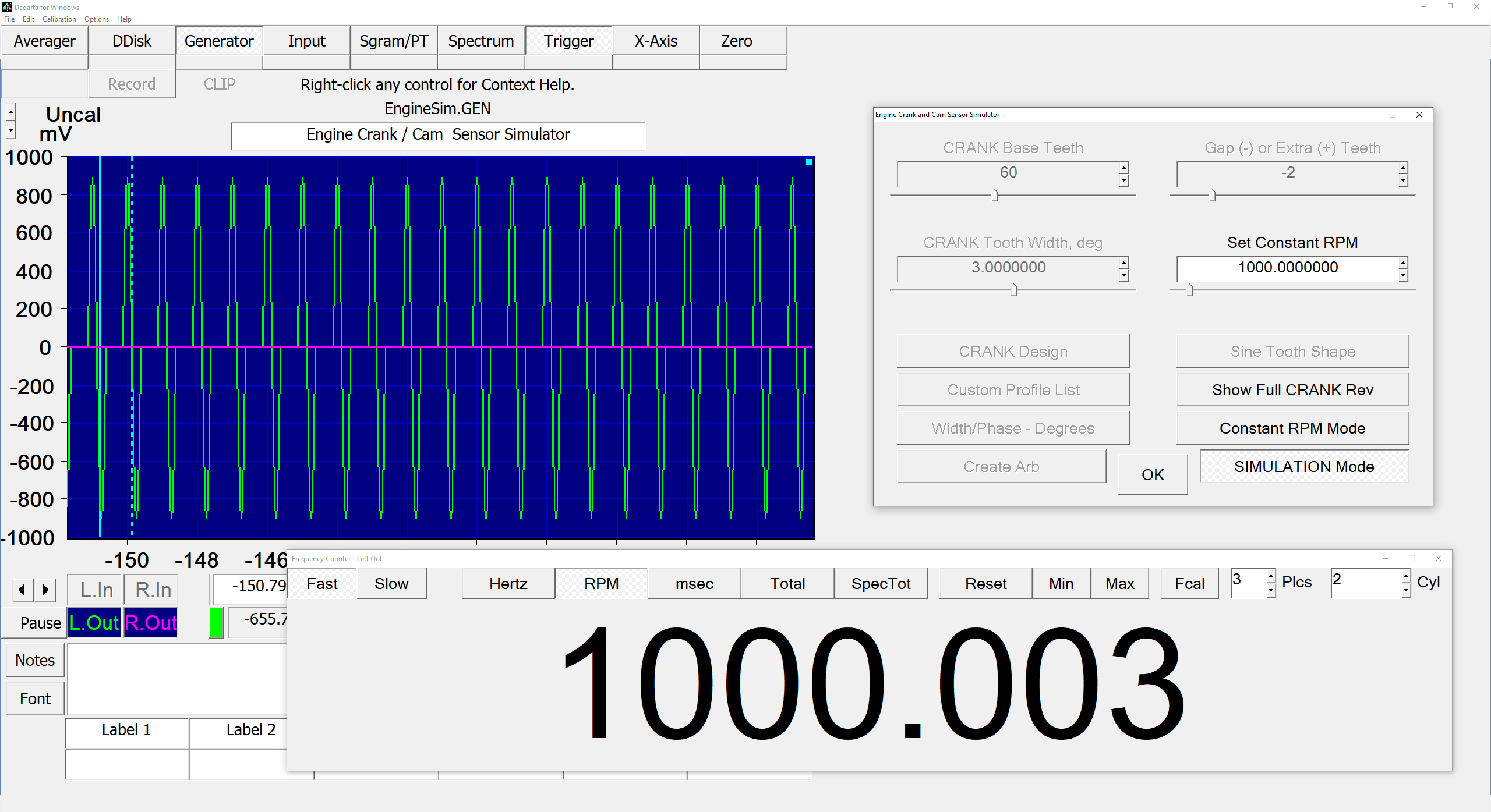
Now I had a controller that I could at least get running on the bench, it was time to start feeding it some signals and see if it will theoretically work when it’s on the car and fed from a trigger wheel. I use Darqarta as a signal generator for various tasks. It’s an excellent piece of software and it also happens to have an engine simulation module in it. From that, you can generate what approximates to a VR sensor signal from your sound card and get it to sweep through an RPM range or set it manually. The only difference is that a soundcard typically produces a single-ended signal whereas a VR sensor produces a differential signal with respect to ground. With a basic op-amp circuit, the single-ended signal could be converted to a differential signal but instead, I did some basic tests by grounding one side of the VR sensor input at the PCB. Maybe not perfect but good enough to get it to fire ignition outputs and produce a tacho signal.
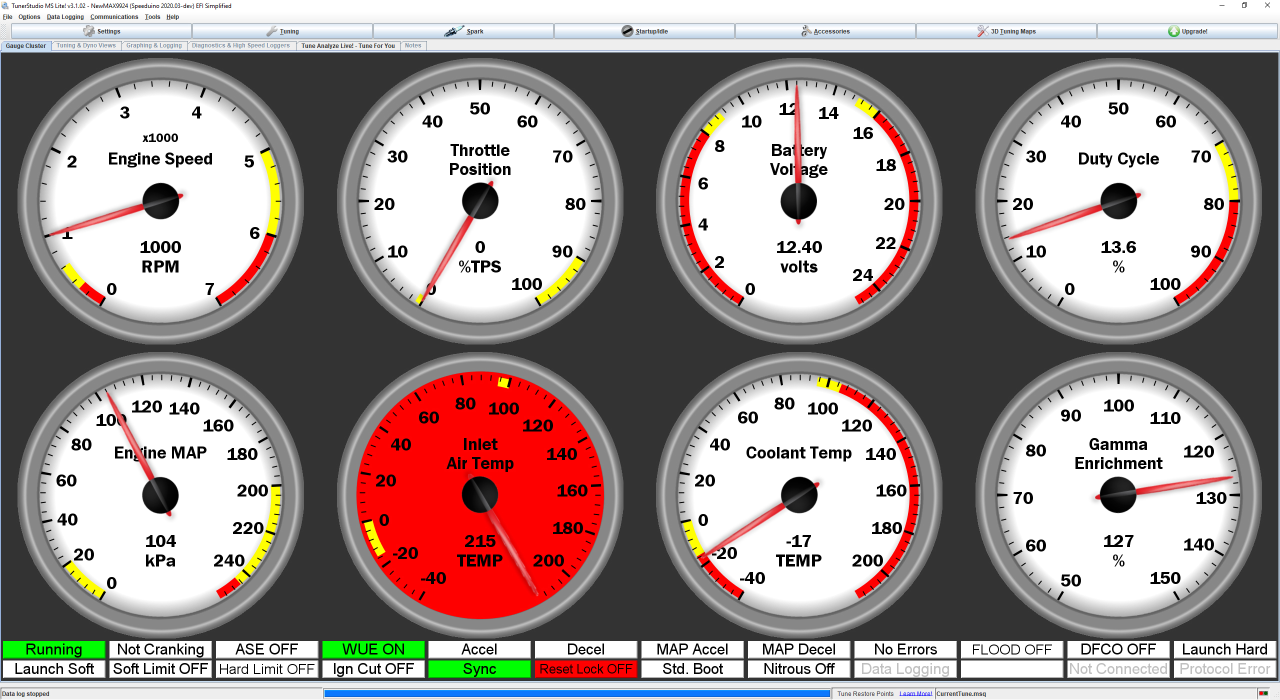
With my new ignition controller flashed with my slightly modified version of the Speeduino firmware, it was connected to TunerStudio and showing me good values for the sensors I had connected. I connected the tachometer from the Spitfire to the output on my board and it worked just fine, too.
So far, so good. At this stage, I realised I had the Bluetooth module connected to the wrong serial port on the Teensy and I wanted to revise the power supply layout so I had to order a modified board. After some messing around to get the Bluetooth working by modifying the pinout in the firmware, I connected RealDash and customised some gauges. Now I could log data to my phone.
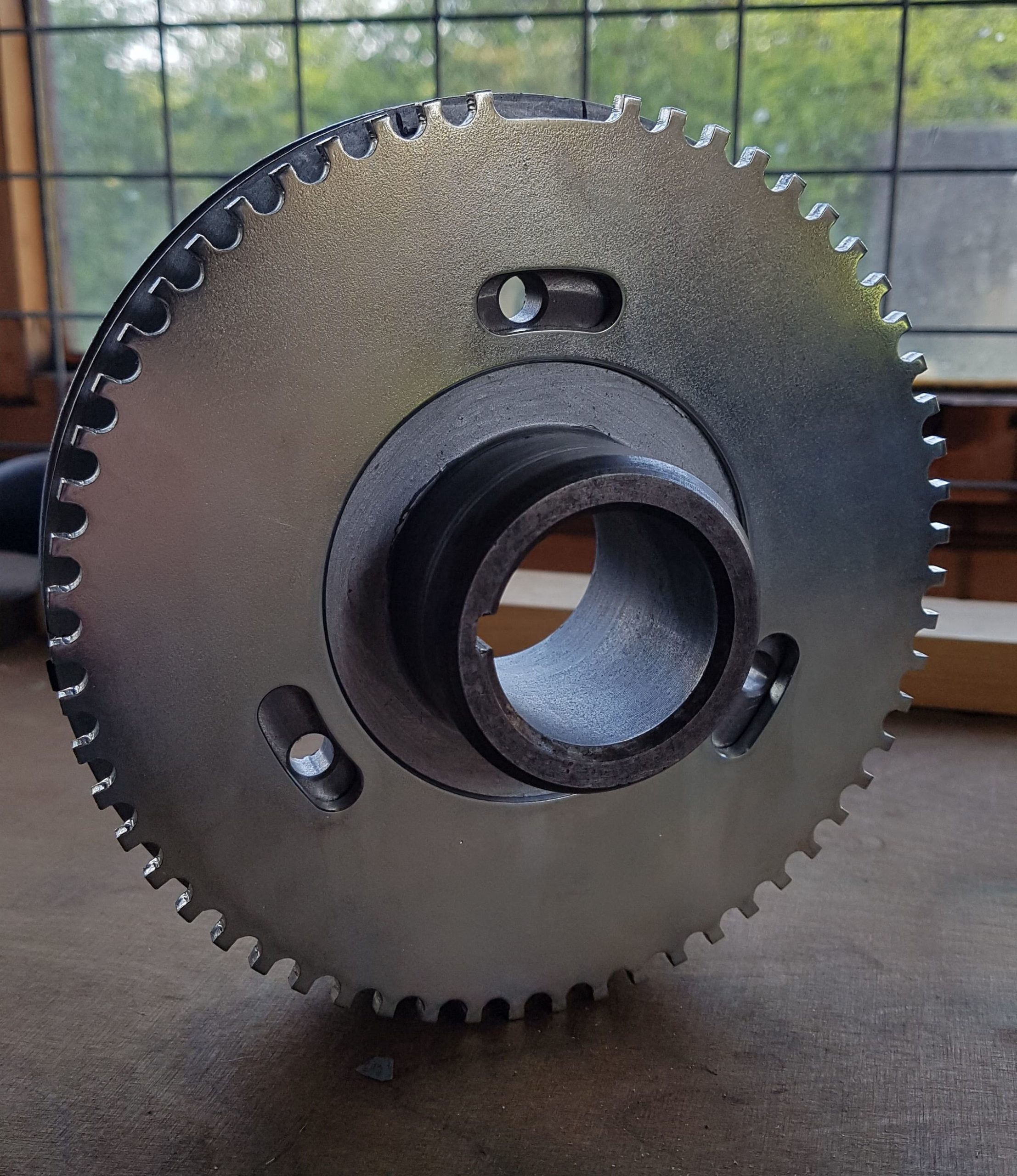
I had a 60-2 trigger wheel and my crank pulley machined so that the wheel sits on the rear of the pulley and made a bracket up for the VR sensor.
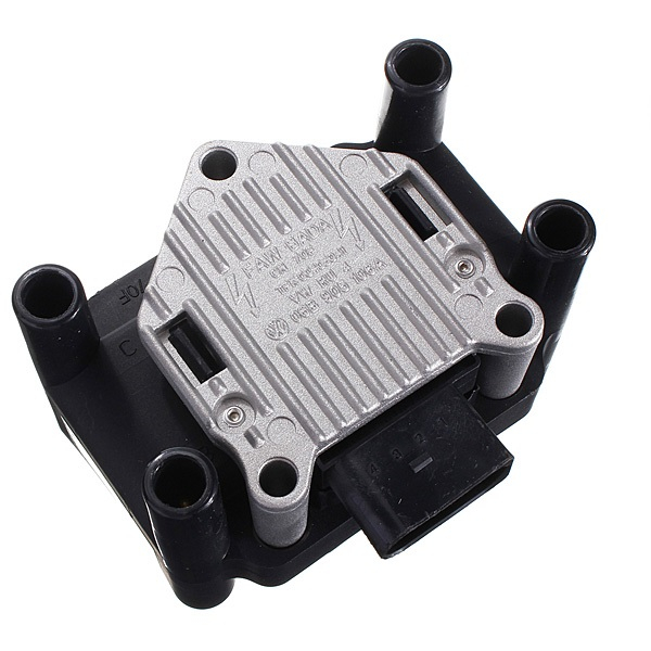
Meanwhile, I’m working on getting the engine ready to start and some of the wiring looms installed which will need some minor modifications to account for my ignition controller. I will fit a relay and fuse module to distribute some of the power from the bulkhead. The coil pack I chose to use is a “smart coil” that is fitted to various VWs which is inexpensive and will produce a much stronger spark than the original oil-filled style. It’s a “smart coil” because it has built-in ignitors and takes a relatively low current, logic-level signal as opposed to a standard coil which requires some form of coil-igniter. Usually, an IGBT (Insulated-Gate Bipolar Transistor) is used to help control back EMF from the primary side of the coil and deliver the high current required to charge the coil.
I ordered appropriate connectors and cable for my coil pack and VR sensor and some push-fit tubing to connect the MAP sensor. The Molex connector I used happens to be the same as an ATX PC motherboard so I cut the connector of an old faulty power supply to start with. I could use that to temporarily wire things in for the initial testing on the engine. I suppose at this stage, having rebuilt the whole engine, testing my newly designed and built ignition system at the same time might be a reach too far but I’m willing to give it a go.
I created a Wiki page to help anyone using my ignition controller in their setup as my contribution to the open-source community.
In my next update, I should be putting all this to the test having plumbed the cooling system in and getting the wiring sorted as far as I need to. Then I get to find out if my engine rebuild was successful…
21 thoughts on “Triumph Spitfire Electronic Ignition”
Fantastic to see people doing this sort of thing, and for putting their work back into the open source community.
Very interesting, and I’d be starting from your setup if I’d not already MegaJolt’d
Very interesting well done do you have plans to release a kit for home assembly?
Once I’ve put this one through its paces then I would consider it for sure.
I would like a kit if available. Nodiz was what I was considering. Great work. How much cost does this system involve.
I’d estimate total cost is about £300-£350 which should get just about everything you would need including the JuiceBox unit, connectors, coil pack, HT leads, trigger wheel, VR sensor and cable. If I was to offer it as a home assembly kit it, I would envisage doing the PCB level assembly myself and just providing the JuiceBox unit with a suitable Molex connector and crimp terminals – probably in the £250 region.
I hope you would consider self assembly too, that’s the fun bit =)
Yes, that’s no problem if you are happy to solder SMD components.
👍 Tats the fun bit
Have you ever used EasyEDA? My design is public so you can download Gerber files and the BOM from there directly if you wanted – EasyEDA – JuiceBox Project
Yes, my Father is an Electrical Engineer it will make a good father son project…. Thanks
Just Wow! Nice work! I really like your design and might use it instead of my old megajolt….
Hello,
First thank for the great job and for sharing it.
I building a Speeduino for a Chevy Small Block 5.7 project, and i looking to build you O2 controller for the LSU4.9.
But i am a little confused, on Oshwlab i get the layout and schematic, but the BOM look to be for the 1.0 version and the rest for the 1.1 version.
Is the program on you GitHub for the 1.0 or 1.1 (or work on both) ?
Is there any advantage to go with the 1.1 version over the 1.0 other than the display ? because i really don’t need the display.
Thanks a lot
I’m part way through v1.1 so the firmware isn’t updated yet. As long as you use a linear voltage regulator with v1.0 you should be fine. Otherwise I’ll have the firmware written for v1.1 in a couple of weeks anyway.
Thanks for reply, ok, i have LM7805 in stock, should be for the 1.0 right ? Thanks again
Yep, an LM7805 should be fine – it’s pin-compatible with the DC-DC converter. The issue I found with v1.0 was that the switching DC-DC module is quite noisy – should be OK with a linear regulator. v1.1 has more filtering on the power supply and is designed to use a linear regulator. I’ve also scaled the output to 0-5V through an op-amp instead of 0-4.3V on v1.0 and added a low pass filter on the output too. The PCB design is slightly improved for noise and thermal and I’ve put slightly larger connectors on v1.1 – the Molex Micro-fit are just a tad small for the kind of wire gauge that you find on a typical O2 sensor. I’m also planning to design an enclosure for v1.1 with two variants, one with and one without the screen that can be 3D printed.
You can use the v1.0 firmware with the v1.1 board and just not fit the display – that would be my preference if you haven’t ordered PCBs/components already. Otherwise, just stick with v1.0 and you should be fine.
Ok, thanks a lot, i will go with the 1.1 PCB and 1.0 Firmware then, look to be the best way.
Thanks again for help.
Hi Joe,
Don’t know if you see my last post about the STD30NF06LT4 replacement with a Through Hole Mosfet, maybe with the PSMN022-30PL ?
I check for the STD30NF06LT4 i only find it in China, claiming it is original ST part, same for the Bosch CJ125, hope that true, did you have any experience with this part from China ?
Thanks again
Hello,
Finally i was able to find all the part and did the 1.1 circuit and finally with the screen that is really nice.
I just get a little issue, for a unknown reason it get stuck with the message PID on the screen and stuck at full heat on the sensor, but never happen a second time, don’t know why, was at the moment to switch to PID just before tell Ready.
Did you know what can cause that ?
And second little issue, in Tuner Studio i put the right calibration value, but it show 14.6 when the screen show 14.7, or 20.30 when the screen get 20.58 i read the voltage and it is 5.0V when AFR at 20.58 on the screen, i suppose that the Speeduino don’t read it exactly, did you get this issue ? i think i should change the calibration value to read it right.
I can only tell you THANKS for all the help and for sharing that nice controller, and if you have a donation link i would be happy to make a donation.
Thanks
Me again, sorry, but just looking for a replacement for the Mosfet STD30NF06LT4, there is no stock, and since i will make my own board to go in a aluminum box i more looking for a Through Hole Mosfet (more easy for me to weld), did you know a reference that can work ? i see the PSMN022-30PL that is really similar, but not sure, part is hard to find today with all shortage.
Thanks for help
Spit 1500 to EFi,I bought twin forties for a vwbug on ebay,chinese knock offs,i want sequential injection,I have the short tract webber manifolds,i need to convert a dizzy or make a cam sensor from scratch on the lathe/mill.
The twin forties will be my iTBs,just to look like i’m “using them” but i’ll add an alloy cover /heat shield over the fuel rail and injectors.
Having never done this,do you have any advise on the cam sensor design,i thought it was just a pulse per rev of the cam,but i’m reading half moon design etc for the trigger pulse.
And please tell me what you are using on your spit to add fuel,carb,EFi…garden sprayer.
Your laycock info helped me a ton,so Big cheers on that mate.
Hi John. I’ll email you some pictures of what I did with an old distributor